STEP 3 – FIREPLACE POSITION ON THE CONCRETE PAD
In order to accomplish Step 3, it is assumed that all combustible forms have been removed
from the fireplace foundation, the ash pit, the combustion air void (if designed in for
fireplace,) the concrete pad, and the hearth extension. Once all combustible forms have
been removed the fireplace furnace is ready for installation on the concrete pad.
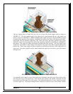
Position the fireplace unit square to the floor and centered over the ash pit opening on top of the
concrete pad. The concrete ash pit opening should be larger than the steel ash pit hole. If this is
not the case, it will be difficult to push ash into the ash pit once the fireplace is in use. Ensure, in
the event that down draft hot air ducts are to be utilized, that the fireplace furnace hot air outlets
align properly with the block outs located in the concrete pad.
As the fireplace furnace is positioned on the concrete pad, verification of dimensions should be
made to ensure proper distances from an inside wall installation or for an outside wall installation.
Verifying that proper clearances have been maintained is important before proceeding to Step 4.
Remove the roll of insulation from its wrapping. Use the insulation to wrap the fireplace furnace
on its top, back, front, and both sides.
STEP 4 – FIREPLACE WALL & CHIMNEY CONSTRUCTION
FIREPL CE WALL CONSTRUCTION – A
Fireplace wall construction is critical to the long term success of the fireplace for several
reasons. The non-combustible brick, concrete, and masonry walls protect the combustible
material that is ultimately used as the core home construction material from the intense
fireplace heat. These same non-combustible walls must support the weight of the chimney
system. Finally, the aesthetics of the masonry work will define the warmth and comfort of all
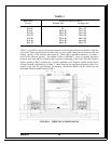
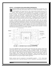
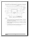
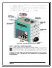
who view the fireplace furnace for years to come. Refer to FIGURE 5 and the following steps
as a guide to installing fireplace walls. Again, local codes and a chimney construction expert
should be involved in the design and construction of the fireplace.
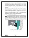
1. The Smart Fireplace Furnace must be enclosed on all sides and back with a minimum of 8”
thick masonry material. It is permissible to use 4” concrete block and standard or common
brick to achieve this eight-inch thickness.
2. 4” CMU (concrete masonry block) should be used for the side and rear walls.
3. The left and right side CMU block walls must frame the Smart fireplace furnace blower
boxes. Frame the blower boxes with CMU block as shown in FIGURE 5.
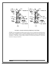
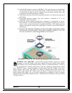
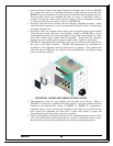
4. CMU side support walls must extend a minimum of 1” above the fireplace unit. These
extended CMU walls will be used for supporting the angle iron that will be used to support
the masonry chimney parts. FIGURE 7 shows the angle iron installation that supports the
chimney brick and the clay flue liner tile.
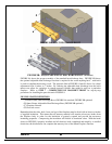
5. An electrical box is preinstalled in the right side of the fireplace. This box is pre-wired for
a snap disk and electrical ground. Before completing the right CMU wall, the electrician
should properly wire the air discharge snap disk. Leave a ½” diameter hole in the right
side CMU block wall. The electrician will need to bring Romex wiring to the electrical
box. The CMU block hole should align with the fireplace furnace electric box cover.
6. The fireplace face brick wall must extend from the floor to the ceiling line.
7. FIGURE 5 shows the insulation installed on the Smart Fireplace exterior sides, front and
back. Insulation also must cover the top of the Smart Fireplace once the chimney is
installed. Compressing insulation reduces its effectiveness. Ensure proper clearance.
Version 7.1
8


