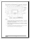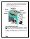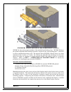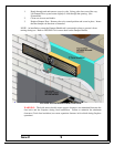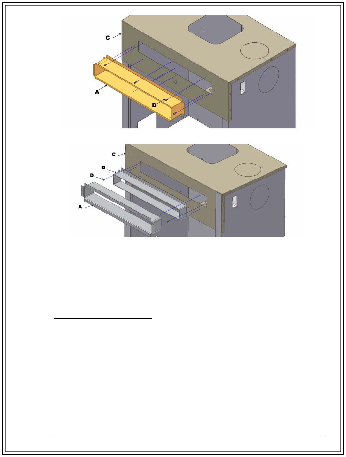
FIGURE 9A: HEAT DISCHARGE BOOT
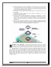
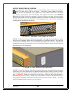
FIGURE 9B: ADJUSTABLE HEAT DISCHARGE BOOT (OPTIONAL)
FIGURE 9A shows the proper assembly of the standard heat discharge boot. FIGURE 9B shows
the optional adjustable heat discharge boot that is required in the event anything but 4” wide brick
is used to complete the masonry work. The optional slide in FIGURE 9, Item B, allows for a lintel
adjustment from 4 inches to 7 inches. By ordering the adjustable heat discharge boot the brick
mason can adjust for variations in custom masonry finishes that might be used on a particular
fireplace. Refer to STEP 7 - COMPLETION OF MASONRY FRONT for step-by-step
procedures for installing the parts shown in FIGURE 9.
FIGURE 9 PARTS DEFINITION
(A) Outer Frame, Heat Discharge Boot (FIGURE 9A standard, FIGURE 9B optional)
(B) Inner Frame, Adjustable Heat Discharge Boot (FIGURE 9B optional)
(C) Fireplace Furnace
(D) Four tek screws
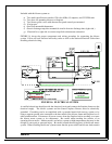
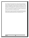
Remember that the sides, back, front, and top of the fireplace must be faced with at least two inches
of supplied insulation. This means that all masonry material will remain at least two inches from
the fireplace body in order for the insulation to properly expand and provide the necessary
insulating properties. Compressing the insulation will reduce its insulation value. With the items
shown in FIGURE 9 properly installed and all electrical work completed and tested by a certified
electrician, the brick mason can complete the masonry face of the Smart Fireplace Furnace.
Version 7.1
15


