


FEATURES AND
OPTIONS
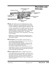
UGE014/0999 Water/Spray Tanks
DESCRIPTION 2-5
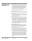
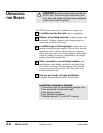
Welded steel frame with
casters and leveling jacks
Stainless steel tank
Air wipe
compartment
Overflow
collector
Hinged fiberglass cover
(optional)
Three-plane adjustment
(optional)
Recirculation reservoir
(optional)
Heat exchanger
(optional)
Recirculation pump
(optional)
● Tank: The stainless steel, all-welded tank has two com-
partments: a long water or spray compartment and a short
air-wipe compartment. Spray header water connections are
stainless steel fittings welded through the tank bottom. The
air wipe compartment has two drilled copper blow-off rings
mounted concentric to the extruded product. The rings are
drilled at an angle to generate water blow-off forces oppo-
site to the direction of extrusion flow. Air supply is
through the front sidewall of the compartment. A throttling
valve is supplied.
Bulkheads are equipped with studs for applying gaskets.
Black gaskets wipe the extruded product. Red gaskets pro-
vide dynamic sealing.
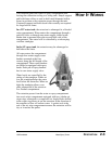
● Tank Support: The tank support system provides for
(1) accurate vertical positioning of each end of the tank to
meet centerline height requirements,
(2) for accurate horizontal positioning of each end of the
tank to meet tank centerline alignment requirements, and
(3) accurate axial positioning of the tank.
The system is comprised of two basic elements: a micro-
height adjusting system to move the tank up and down and
a tank cradle system that cages the tank and carries means
for horizontal and axial positioning.
● Water Supply System: Water is supplied from a short
water supply header carried on the tank. A ball valve con-
trols water to each spray header. This valve is used to mod-
ulate water to the tank. On small water tanks with one
spray header, the second valve is used for "quick fill". On
long tanks a third ball valve directs water to an end port to
assist in "quick fill".