


9
Gas Fireplace Insert
10002964
Common Flue Installations
In some areas it is possible to vent more than one gas
fireplace into the same flue. You must ensure the flue
being shared has the proper capacity to handle both
fireplaces. Check installation codes for venting capacity
information.
As always it is best to check with the authority having
jurisdiction prior to commencement of the installation.
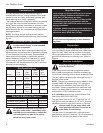
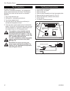
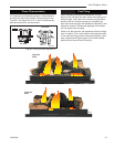
Liner Installation
Insert liner from top of chimney through the damper
opening and attach to 3" flue collar (for A125); 4" flue
collar (for A132). For best results use three (3) sheet
metal screws and a hose clamp.
For natural draft inserts, packing fibreglass insulation
around the liner in the damper area will isolate the fire-
place cavity from the chimney and prevent drafts and
noises during operation.
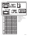
In case the fireplace opening is only minimum height
(17¹⁄₂" for A125) (20" for A132) and access from the
front is not possible, remove the flue collar plate - un-
screw and slide out from the back of the unit. Now
attach the liner to the flue collar, lift up and simply slide
flue collar plate back onto the unit top. It is important
the plate is completely inserted and the front screw is
fastened again in order to line up the flue outlet and the
liner properly. (Fig. 10)
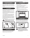
If fireplace lintel is wider than 8" (203 mm),
the height of the fireplace opening must
be 25" (635 mm) to allow for a 90° offset
elbow to be installed.
FP1354a
RHE
Flue outlet
6/03
Damper
Flue
Collar Plate
Clamp
Chimney
Liner
Screw
Chimney Liner
Damper
Clamp
FP1354a
Fig. 10 Remove flue collar plate and attach to flue collar.
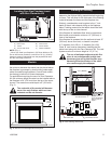
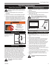
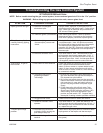
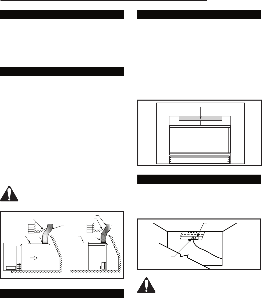
Draft Relief Opening
This insert is equipped with a draft-relief opening which
receives its dilution air supply through the opening
behind the louvres. These openings must not be
obstructed or altered in any way. (Fig. 11)
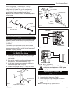
Test Chimney Draw
A "Chimney Draw" test must be made before the
installation is complete.
1. Close all doors and windows in the home and start
exhaust fans in the kitchen and bathroom.
2. Light unit and operate for 5 minutes.
3. Hold an ignited match or cigarette in front of the unit.
Refer to Figure 11 for the location of the draft hood
opening.
4. Check to make sure smoke from the match or
cigarette is drawn into the fireplace. If it is not, turn
the unit off and check for causes creating the lack of
adequate draft.
FP1371
RHE test
chimney
6/03
Test for Draft at This Location
FP1371
Fig. 11 Hold an ignited match in front of fireplace.
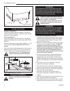
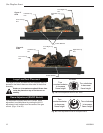
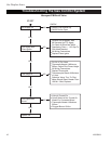
Vent Safety System
These inserts are equipped with a vent safety shut
down switch. This switch is factory installed, wired and
tested. Check and make sure the switch and wires are
in the proper position. The safety switch is heat activat-
ed and wired in series with the pilot system. (Fig. 12)
FP1372
Vent safety
switch
6/17/03 djt
Bracket
Vent Safety
Switch
FP1372
Fig. 12 Vent safety switch.
Operation of this fireplace when not
connected to a properly installed and
maintained venting system or tampering
with the vent safety shutoff system can
result in carbon monoxide (CO) poisoning
and possibly death.