


20
Gas Fireplace Insert
10002964
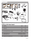
Ceramic Refractory
Optional for A125 and A132
Model Description
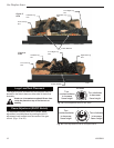
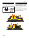
RHE25CR Ceramic Firebox Liner
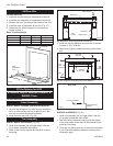
1. Remove front glass (Refer to Glass Frame Removal
section)
2. Remove logs from unit.
Logs may be hot!
3. Remove refractory from packaging.
Refractory are fragile and must be handled with
care. Where at all possible, two hands should be
used when handling.
4. Take center refractory and tilt so bottom edge slides
into support angle in back of fireplace.
5. Now press center refractory to back side of fireplace
and hold in place.
6. Take left or right refractory and align it so leading
edge faces outward. Place refractory in fireplace
side and slide it back to support center refractory.
7. Install metallic piece in the leading edge (A132 only).
8. Repeat Step 6 and 7 for remaining side refractory.
When side refractory is installed correctly,
the center refractory will be supported by
the side refractory.
9. Fasten top tab supports against refractory to hold
sides in place.
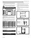
Optional Accessories
Left Side
Center
Right Side
Leading
Edge
Bottom Edge
FP1278
Fig. 24 Ceramic refractory.
Leading
Edge
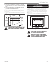
Zero Clearance Kit
For installations other than in existing woodburning fire-
places such as new construction or renovation projects,
a Zero Clearance Kit must be used. The HEZC enables
these inserts to be installed in combustible environ-
ments. It is recommended that an Air Kit (AKZC) be
installed whenever using a Zero Clearance Kit. Con-
sideration must be given to the dimensions of the Zero
Clearance Kit and the requirements of the Air Kit when
planning out the installation.
Follow the instructions supplied with the Zero Clearance
Kit carefully for proper installation.
Remote Controls
Optional remote control units are available to control
different functions of the appliance.
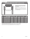
Model Function(s) Controlled
RC1 ON/OFF
RC2 ON/OFF and Temperature
IMTFK Wall mounted thermostat control
A Trim Options for A125
A1 RHE25SSP, RHE25LP
Trim Assembly
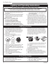
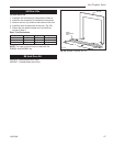
RHE25SSP
1. Install trim channels (left and right sides). Use two
screws to assemble each piece.
2. Slide on the trim top channel and fasten it from the
back side.
3. Install the trim top deflector using two screws.
4. Remove ALL plastic protective covering from brass
trim.
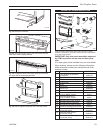
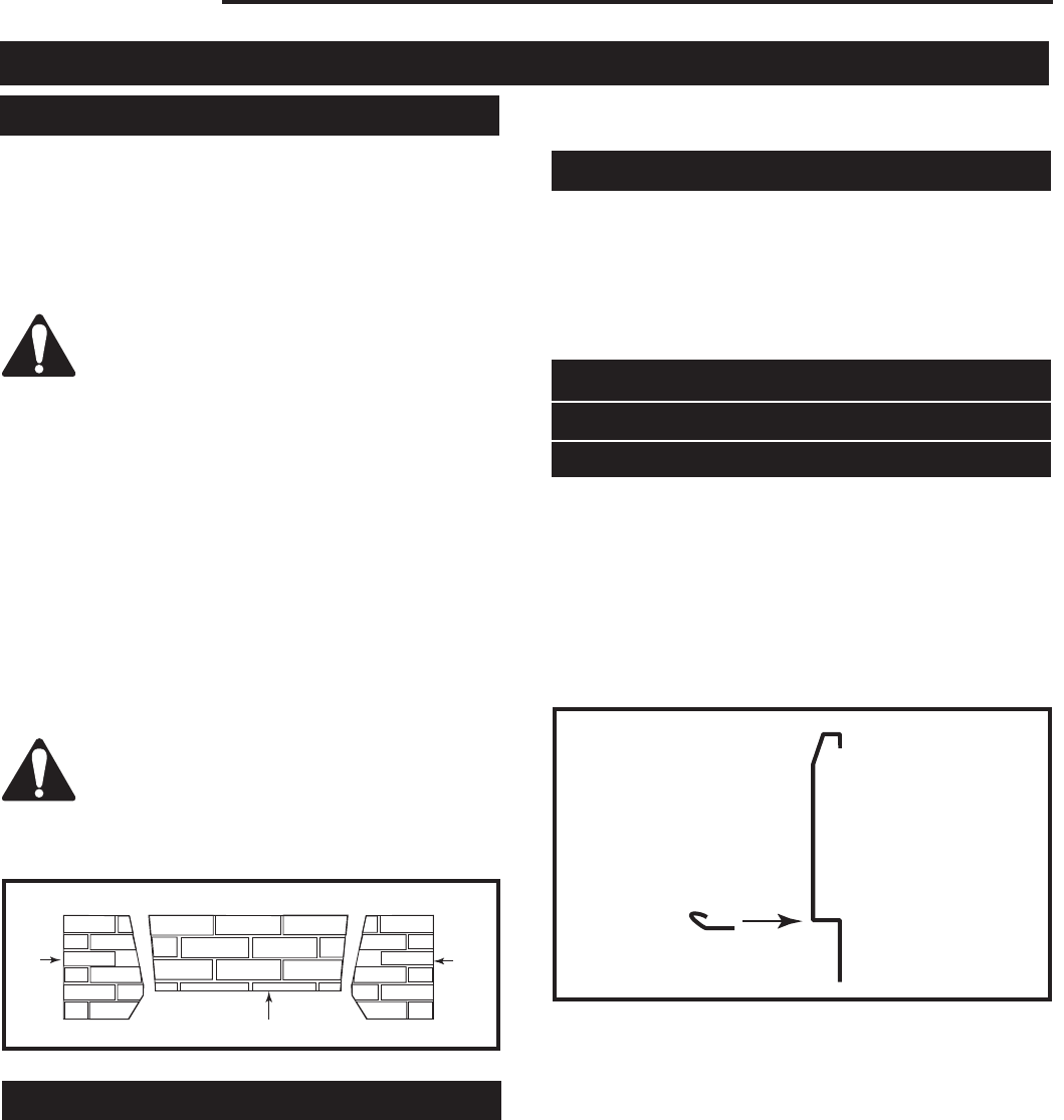
FP1261
deflector
1/03
Trim Top Deflector
Trim Frame Top Section
Side View
FP1261a
Fig. 25 Trim top deflector.
HE25LP
1. To install the kit you do not have to remove any
piece of brass, you just add the external pieces.
2. Remove the frame trim from the unit if it is already
installed.
3. Install trim channels (left and right sides) by remov
-
ing the two screws that hold the side brass trim and
put them back to hold both parts.
4. Slide on the trim top channel and fasten it from the
back side.