


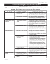
11
Gas Fireplace Insert
10002964
Operating Instructions
General Glass Information
Only ceramic glass approved by CFM Cor-
poration may be used for replacement on
this unit.
1. The use of substitute glass will void all product
warranties.
2. Care must be taken to avoid breakage of the glass.
3. Under no circumstances should this appliance be
operated without glass properly installed, or with any
cracked or broken glass. Replacement of any glass
assembly as supplied by the manufacturer should be
done by a licensed qualified service person.
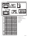
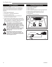
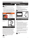
1.
2.
Louvre
Glass
Panel
FP444
Fig. 15 Louvre removal.
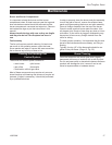
Glass Cleaning
It will be necessary to clean the glass periodically.
During start-up, condensation, which is normal, forms
on the inside of the glass and causes lint, dust and
other airborne particles to cling to the glass surface.
Also initial paint curing may deposit a slight film on
the glass. It is therefore recommended the glass
be cleaned two or three times with a non-ammonia
household cleaner and warm water (we recommend
gas fireplace glass cleaner). After that the glass should
be cleaned two or three times during each heating
season depending on the circumstances present.
Clean glass after first two weeks of
operation.
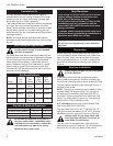
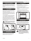
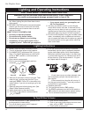
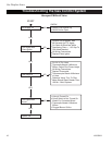
Glass Frame Removal
1. Remove the top louvre. (Refer to “Louvre Removal”
section)
2. Open access door.
3. Remove two (2) machine screws from the bottom of
glass frame. (Fig. 16)
4. Lift up and unhook glass frame at the top.
Before remounting glass frame, brass
trim must be installed. Refer to “Frame
Mounting” section.
�
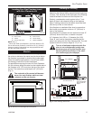
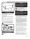
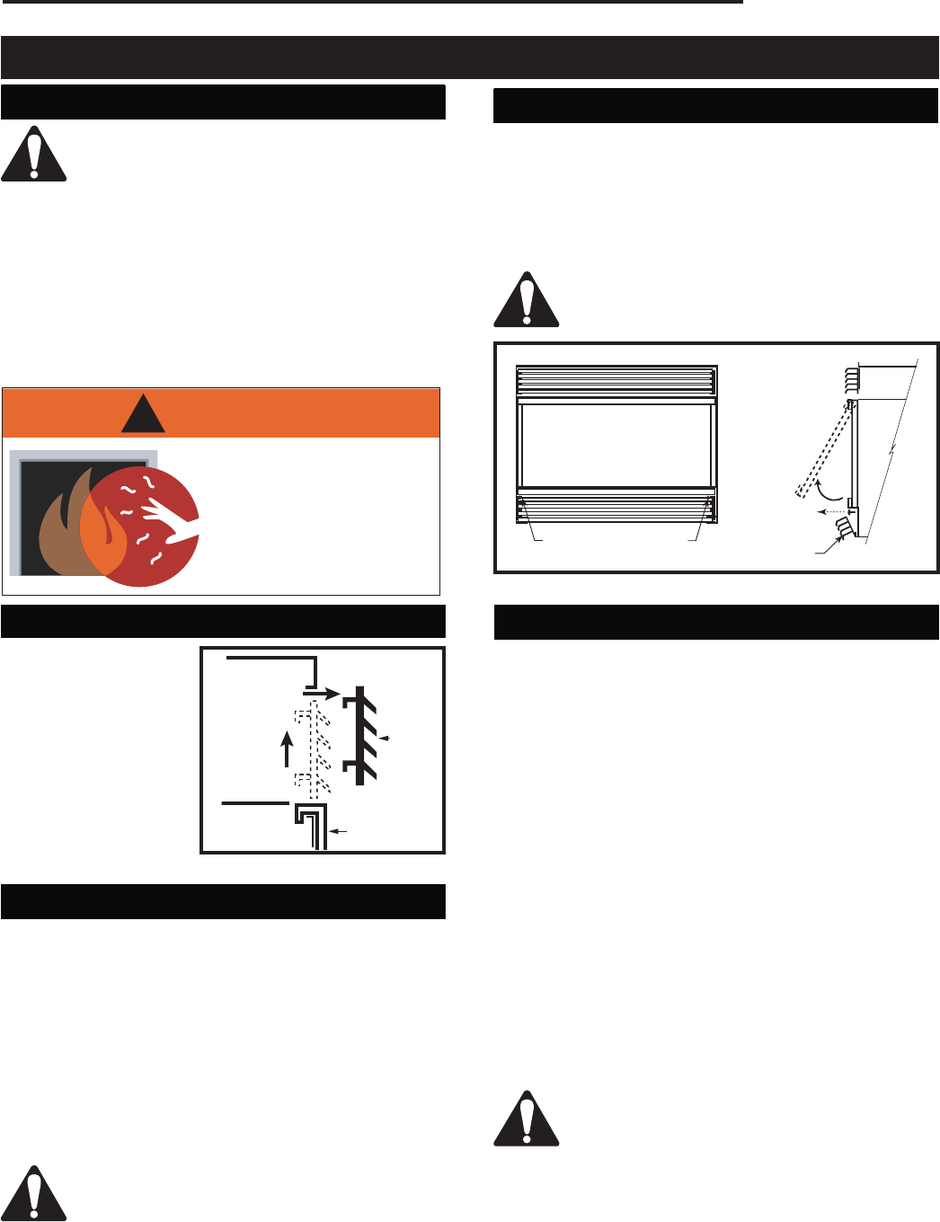
Louvre Removal
To remove top flat lou-
vre pull louvre up and
then lift out.
FP1373
RHE
window frame
removal
6/03
Screws
Open Access Door
Machine Screws
Glass Frame
FP1373
Fig. 16 Remove glass frame.
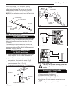
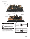
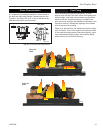
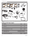
Installation of Logs and Ember Material
Refer to Figures 17 & 18
1. Remove front glass. (Refer to "Glass Removal" sec
-
tion)
2. Remove logs from packaging.
3. Place left rear log (N15 or N17) by using the log’s
bottom holes to locate it into the two pin studs lo-
cated on the left side of the rear log support.
4. Place right rear log (N16 or N18) by using the log’s
bottom holes to locate it into the two pin studs lo-
cated on the right side of the rear log support.
5. Place front right log (N14 or N20) onto locator
notches. Ensure the log is securely in place.
6. A125: Place front left log (N13) onto locator. Ensure
the log is securely in place.
A132: Place front left log (N19) against the back of
the left burner heat shield and the front edges of the
log should be flat against the front deflector.
7. Place ember material on to the front area of the
burner.
Top logs must be placed properly into
notches.