


5
Gas Fireplace Insert
10002964
Locating Your Gas Fireplace Insert
with Zero Clearance Kit
C
D
B
E
A
F
X
X
X
FP1249a
locating DV unit
with zero clearance kit
4/03
FP1249a
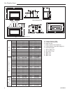
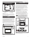
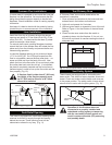
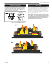
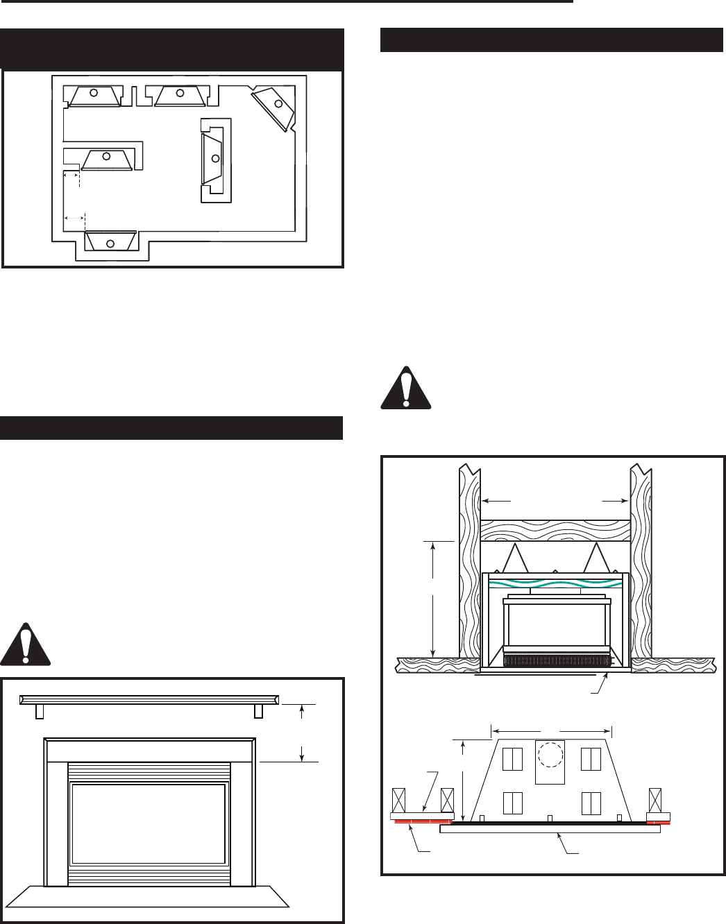
Fig. 1 Locating unit with zero clearance kit.
A) Flat on wall B) Cross corner
C) Island D) *Room divider
E) *Flat on wall corner F) Chase installation
NOTE: (Fig. 1)
* When you install your fireplace in (D) Room divider or (E)
Flat on wall corner positions, a minimum of 6” (X) (153mm)
clearance must be maintained from the perpendicular wall
and the outer edge of the trim.
Mantels
When the unit is installed into a woodburning fireplace,
the minimum distance the mantel can be placed above
the fireplace is governed by local building codes appli-
cable to woodburning fireplaces. Consult local authori-
ties having jurisdiction for these clearances.
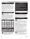
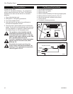
For applications requiring the use of a Zero Clearance
Kit, the minimum height a mantel can be installed above
the fireplace is 24" (610 mm) from the top of the upper
louvres. The maximum mantel depth is 8" (203 mm).
(Fig. 2)
The underside of the mantel will become
warm. Use only finishes which are heat
resistant and do not discolor.
FP1325
Insert mantel
height
4/1/03 djt
24" Min.
(610mm)
FP1325
Fig. 2 Minimum mantel height above fireplace.
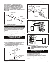
Framing & Finishing
For Zero Clearance Kit applications, it is important to
determine the finished facing material before beginning
to frame. This will allow for the thickness of the finishing
material between the frame and the fireplace trim.
Similarly, consideration must be given to the 1" inch
depth of the air inlet channel sitting on the fireplace
base. Finishing material for the hearth should be flush
with the top of the air inlet channel.
If the fireplace is installed at floor level a noncombus-
tible hearth must extend a minimum 12" (305 mm) in
front of the fireplace.
If the fireplace is recessed into the wall and at least 12"
(305 mm) above floor level, no hearth is required.
A 3” diameter (for A125) or 4” diameter (for A132)
Class ‘B’ vent must be used when installing the fire
-
place insert along with the Zero Clearance Kit. The vent
system must be a minimum height of 12’ (3.7 m)
The use of wallpaper adjacent to this fire
-
place is not recommended as high tem-
peratures given off by this fireplace may
adversely effect the binders in the adhe-
sive used to apply the wallpaper.
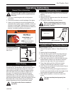
K
37" (946mm)
FP1251
Insert framing
and finishing
1/03
P
O
Air Inlet Channel
Drywall
Finish Wall
Decorative Trim Kit
FP1351
Fig. 3 Insert framing dimensions.
NOTE: For K, O
and P dimensions,
refer to chart on
Page 4