


8
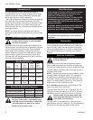
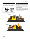
Gas Fireplace Insert
10002964
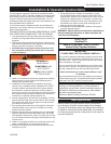
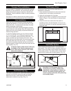
Leveling Bar
Set Screws
FP1658
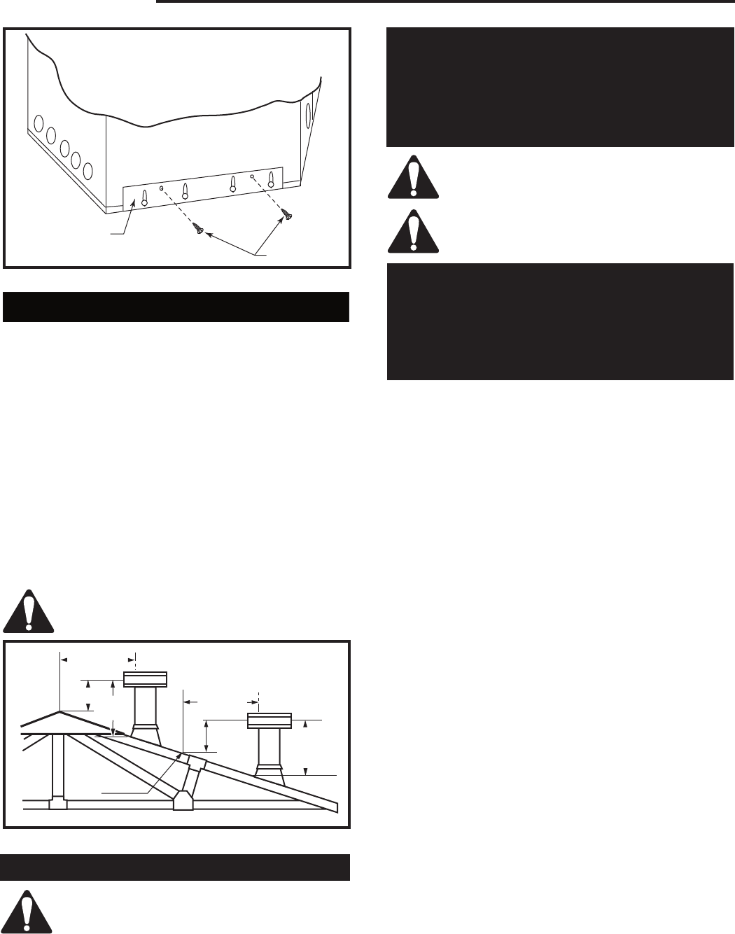
Fig. 8 Adjust leveling bar on A132 only.
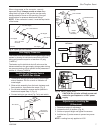
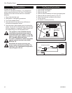
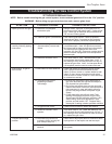
2' Min.
2'
(610mm)
Min.
3'
Min.
0 To 10'
3'
(914mm)
Min.
0 To 10'
AC246
4/1/96
Reference
Point
(3m)
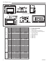
Fig. 9 Example of the 2', 3', 10' rule.
AC246a
Venting and Installation
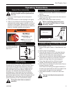
Installer must attach red warning label to
fireplace.
WARNING
This fireplace has been converted for use with
gas only and cannot be used for burning wood
or solid fuels unless all original parts have been
replaced and the fireplace has been re-approved
by the authority having jurisdiction.
Cutting any sheet metal parts of the fire-
place, in which the gas fireplace insert is
to be installed, is prohibited.
Ensure there are no obstructions to side
air passages of decorative trim once in-
stalled on insert.
WARNING
Some factory built fireplaces have air passages
on face of fireplace for zero clearance capabili-
ties. All trim kits are designed so as to allow air-
flow to these passages. Under no circumstances
should these passages be blocked.
Venting Instructions
Canadian Installations:
The venting system must be installed in accordance
with the current CSA-B149.1 installation code, and the
authority having jurisdiction.
U.S.A. Installations:
The venting system must be installed in accordance
with the current National Fuel Gas Code, ANSI Z223.1/
NFPA 54.
Minimum clearances to combustible materials is 1" (25
mm) for B Vent (use of single wall vent is not al-
lowed).
As with any natural draft appliances, the vent cap must
always extend a minimum of 2' (610 mm) above any
structure within a 10' (3 m) horizontal plane. (Fig. 9)
A minimum 12’ (3.7 m) vent height is re
-
quired to effectively vent this fireplace.
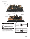
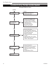
1. Gas inserts are designed for recessed
installations into solid fuel masonry or factory built
noncombustible fireplaces that have been installed
in accordance with the National, Provincial, State
and local building codes.
2. Measure for minimum fireplace opening requirement
on Page 4 of this installation manual. (If firebrick
[refractory] is removed from a factory built
fireplace in order to gain minimum gas fireplace
insert opening requirements, a minimum of 1/4"
(6 mm) air space is required between the gas
insert fireplace's outer casing and the inner wall
of the factory built fireplace).
3. To assure top performance, safety and efficiency,
all inserts must be installed with an approved 4"
diameter flue liner, with exception of A125, which
should be installed with an approved 3" liner,as per
CSA-B.149 or National Fuel Code ANSI Z223/NFPA
54.
4. Flue damper must be fully blocked in the open
position or removed for installation.
5. The chimney must be clean and in good working
order and constructed of noncombustible materials.
6. Make sure that all chimney cleanouts fit properly so
air cannot leak into the chimney.
7. Glass door, screen kits and log grate may be
removed for installation of insert into factory built
fireplace.
8. Install the insert without the trim frame and make all
gas, venting and electrical connections.
9. Install decorative trim frame. Please refer to Frame
Assembly and Mounting instructions In this manual.