


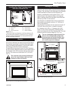
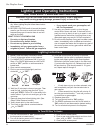
7
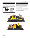
Gas Fireplace Insert
10002964
CFM106
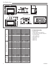
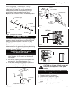
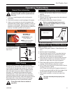
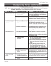
Typical Gas Line Connection
9-29-00
1/2” Gas Supply
1/2” x 3/8” Reducer
3/8” Nipple
3/8” x 3/8” Shut
Off Valve
3/8” Nipple
3/8” Union
3/8” Nipple
CFM106
Fig. 4 Typical gas line installation.
When using copper or flex connector, use only
approved fittings. Always provide a union when
using black iron pipe so the gas line can be easily
disconnected for burner or fan servicing. See gas
specifications for pressure details and ratings.
NOTE: If flex connector is used, it must be kept inside
of the heater.
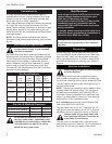
Gas Supply Pressures
This heater must be isolated from the gas supply piping
system by closing its individual manual shut-off valve
during any pressure equal to or less than 1/2 psig
(3.45kPa).
The heater and its individual shut-off valve must be
disconnected from the gas supply piping system during
any pressure testing of that system at test pressures in
excess of 1/2 psig (3.45kPa).
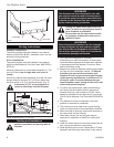
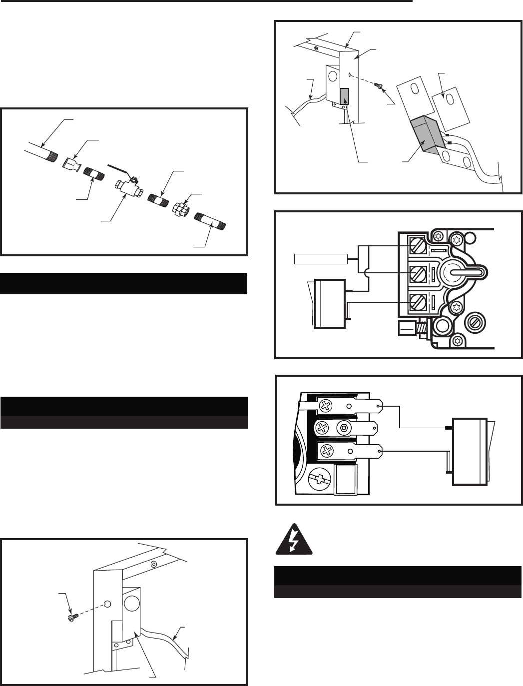
Installation of Remote Switch
for RN/RP Gas Valves
1. Thread wire through gas inlet opening on the right
side of fireplace. Do not cut wire or insulation on
metal edges.
2. Slide switch assembly from the back, between sub-
frame and trim, then fasten the screw. (Fig. 5)
3. For left side installation reverse switch position in
bracket and repeat Step 2. (Fig. 6)
4. Connect wiring to gas valve (Fig. 7a,b) and switch.
Trim Screw
Wiring from
Millivolt Gas
Valve
On/Off Switch Assembly
FP1657
Fig. 5 Install switch between subframe and trim.
Trim Top
Trim Left Side
Bracket Switch
Trim
Screw
Wiring
from
Millivolt
Gas
Valve
On/Off
Switch
Assembly
FP1657
Fig. 6 Left side switch installation.
TPTH
TH
TP
FP1218a
Remote switch
wiring - rocker
1/03
FP1218a
Fig. 7b ON/OFF switch wiring.
P
I
L
O
T
THTP
TP
TH
FP382a
REMOTE SWITCH WIRING - NVC
1/03
SIT Valve
Thermopile
FP382a
Fig. 7a On/Off switch or millivolt thermostat.
CAUTION: Do not wire millivolt remote wall
switch for gas fireplace to a 120 V power
supply.
Adjustment of Leveling Bar
(If Required)
1. Determine height of adjustment.
2. Loosen the four (4) screws. (Fig. 8)
3. Set bar at proper height and tighten the screws.
4. Add the two (2) extra screws to prevent any move-
ment.
NOTE: Leveling bar only applies to A132.