


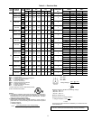
9
Voltage to compressor terminals during operation must be
within voltage range indicated on unit nameplate (see Table 2).
On 3-phase units, voltages between phases must be balanced
within 2% and the current within 10%. Use the formula shown
in the legend for Table 2, Note 2 to determine the percent of
voltage imbalance. Operation on improper line voltage or ex-
cessive phase imbalance constitutes abuse and may cause dam-
age to electrical components. Such operation would invalidate
any applicable Carrier warranty.
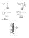
FIELD CONTROL WIRING — Install a Carrier-approved
accessory thermostat assembly according to installation in-
structions included with the accessory. Locate thermostat
assembly on a solid wall in the conditioned space to sense aver-
age temperature in accordance with thermostat installation
instructions. Connect thermostat wires to terminal board.
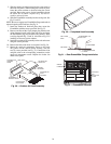
Route thermostat cable or equivalent single leads of colored
wire from subbase terminals through connector on unit to low-
voltage connections (shown in Fig. 12).
NOTE: For wire runs up to 50 ft, use no. 18 AWG (American
Wire Gage) insulated wire (35 C minimum). For 50 to 75 ft,
use no. 16 AWG insulated wire (35 C minimum). For over
75 ft, use no. 14 AWG insulated wire (35 C minimum). All
wire larger than no. 18 AWG cannot be directly connected to
the thermostat and will require a junction box and splice at the
thermostat.
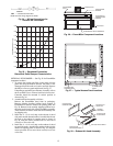
Feed control wires through the raceway located between the
condenser coil top cover and burner side panel. See Fig. 10.
Connect control wires to corresponding screw terminals, the
low-voltage connections located inside low-voltage access
panel. See Fig. 12 for connections. The low-voltage connec-
tions provide the UL required clearance between high- and
low-voltage wiring.
HEAT ANTICIPATOR SETTINGS — Set heat anticipator
settings at .14 amp for the first stage and .14 amp for second-
stage heating, when available.
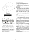
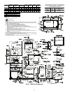
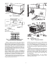
CONDENSER
COIL
TOP COVER
INTAKE
LOUVERS
CORNER POST
FLUE HOOD
END PANEL
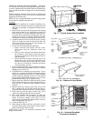
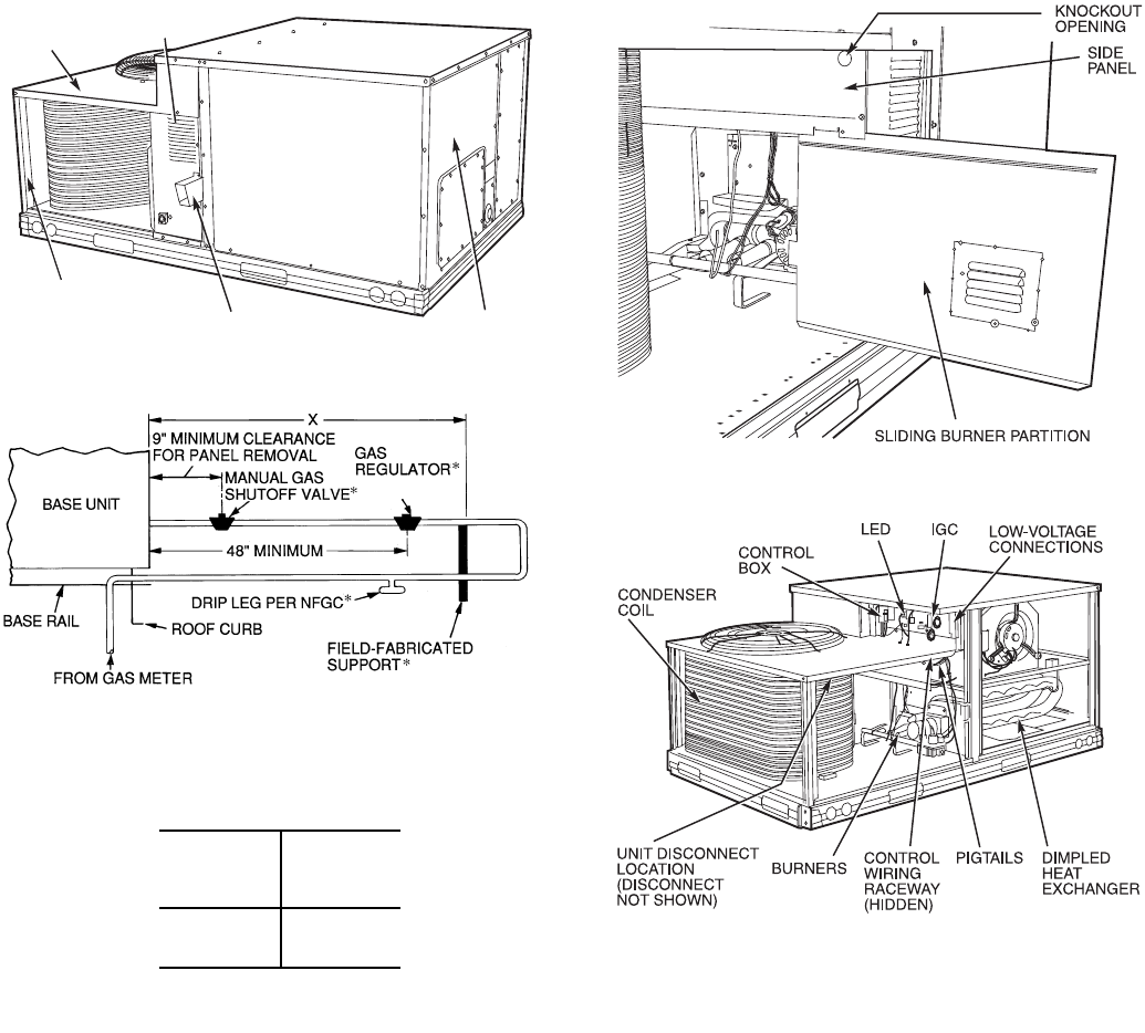
Fig. 8 — Gas Piping Guide (With Accessory
Thru-the-Curb Service Connections)
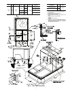
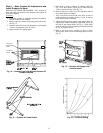
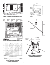
SPACING OF SUPPORTS
STEEL PIPE
NOMINAL
DIAMETER
(in.)
X
DIMENSIONS
(feet)
1
/
2
3
/
4
or 1
1
1
/
4
or larger
6
8
10
LEGEND
*Field supplied.
NOTE: Follow all local codes.
NFGC —
National Fuel Gas Code
Fig. 7 — Flue Hood Details
Fig. 9 — Conduit Installation
LEGEND
Fig. 10 — Component Location
IGC —
Integrated Gas Unit Controller
LED —
Light-Emitting Diode