


5
Step 7 — Make Electrical Connections
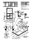
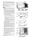
DISCONNECT BOX LOCATION — The field-supplied dis-
connect box may be mounted on the unit’s end panel or on the
corner post. Mount disconnect box on the left side of the rating
plate when mounting on the unit’s end panel.
Do not mount the
disconnect box over the unit rating plate.
When mounting
disconnect box on corner post, secure disconnect box to corner
post and condenser coil top cover. See Fig. 7.
A disconnect box mounting space is available when an op-
tional or accessory condenser coil grille is used. Mount the dis-
connect on the sheet metal provided with the condenser coil
grille. The sheet metal is located adjacent to the corner post on
the left side of the power wiring access panel.
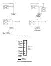
FIELD POWER SUPPLY — All units except 208/230-v
units are factory wired for the voltage shown on the nameplate.
If the 208/230-v unit is to be connected to a 208-v power sup-
ply, the transformer
must
be rewired by disconnecting the black
wire from the 230-v terminal wire on the transformer and con-
necting it to the 200-v red terminal of the transformer.
Refer to unit label diagram for additional information. Wir-
ing leads are provided for field service. Use copper conductors
only when splice connectors are used.
When installing units, provide a disconnect per NEC.
All field wiring must comply with NEC and local require-
ments. In Canada, electrical connections must be in accordance
with CSA (Canadian Standards Association) C22.1 Canadian
Electrical Code Part One.
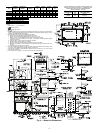
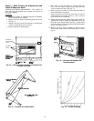
Install field wiring as follows:
1. Connect ground lead to chassis ground connection when
using separate ground ties.
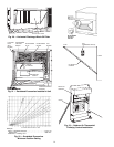
2. Install conduit between disconnect and side panel. Insert
conduit through power supply knockout opening. See
Fig. 9.
3. Connect power lines to power wiring leads.
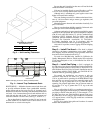
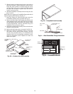
4. Pigtails are provided for field power connections and are
located inside the burner access panel. See Fig. 10 and 11.
Use factory-supplied splices or Underwriters’ Laborato-
ries (UL) approved copper connector.
Unit cabinet must have an uninterrupted, unbroken electri-
cal ground to minimize the possibility of personal injury if
an electrical fault should occur. This ground may consist of
electrical wire connected to unit ground lug in control com-
partment, or conduit approved for electrical ground when
installed in accordance with NEC (National Electrical
Code), ANSI/NFPA, latest edition, and local electrical
codes.
Do not use gas piping as an electrical ground.
Fail-
ure to follow this warning could result in the installer being
liable for personal injury of others.
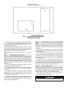
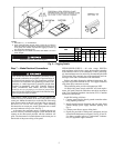
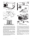
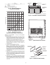
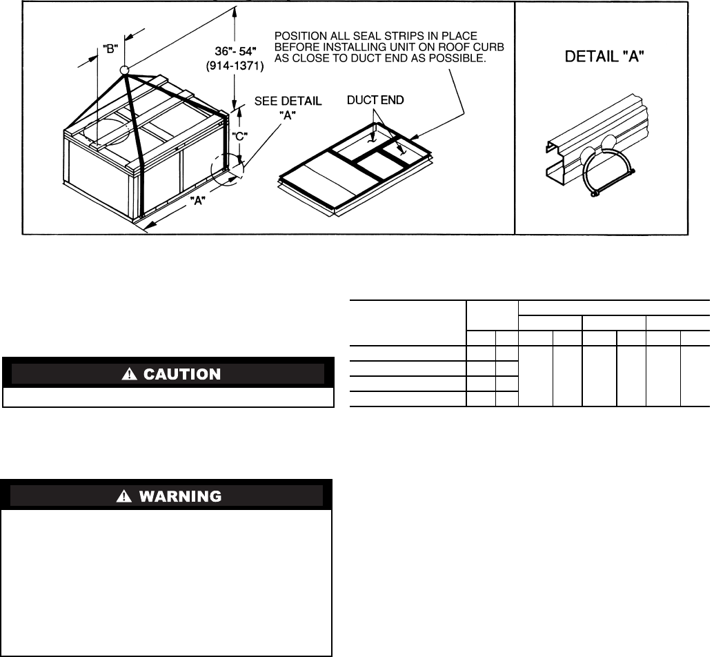
NOTES:
1. Dimension in ( ) is in millimeters.
2. Hook rigging shackles through holes in base rail, as shown in
detail ‘‘A.’’ Holes in base rails are centered around the unit cen-
ter of gravity. Use wooden top skid when rigging to prevent rig-
ging straps from damaging unit.
3. Unit weights do not include economizer. See Table 1 for econo-
mizer weights.
All panels must be in place when rigging.
Fig. 5 — Rigging Details
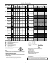
UNIT
MAX
WEIGHT
DIMENSIONS
‘‘A’’ ‘‘B’’ ‘‘C’’
lb kg in. mm in. mm in. mm
48TJE,TJF004
510 231
73.69 1872 37.50 953 33.35 847
48TJD,TJE,TJF005
520 236
48TJD,TJE,TJF006
540 245
48TJD,TJE,TJF007
615 279