


Manufacturer reserves the right to discontinue, or change at any time, specifications or designs without notice and without incurring obligations.
PC 111 Catalog No. 534-774 Printed in U.S.A. Form 48TJ-18SI Pg 1 10-00 Replaces: 48TJ-16SI
Book 1 4
Ta b 1 a 6 a
Installation, Start-Up and
Service Instructions
CONTENTS
Page
SAFETY CONSIDERATIONS
. . . . . . . . . . . . . . . . . . . . . . 1
INSTALLATION
. . . . . . . . . . . . . . . . . . . . . . . . . . . . . . . . 1-36
Step 1 — Provide Unit Support
. . . . . . . . . . . . . . . . . . . 1
•ROOF CURB
• SLAB MOUNT
Step 2 — Field Fabricate Ductwork
. . . . . . . . . . . . . . . 2
Step 3 — Install External Trap for
Condensate Drain
. . . . . . . . . . . . . . . . . . . . . . . . . . . . . . 2
Step 4 — Rig and Place Unit
. . . . . . . . . . . . . . . . . . . . . 2
• POSITIONING
Step 5 — Install Flue Hood
. . . . . . . . . . . . . . . . . . . . . . . 4
Step 6 — Install Gas Piping
. . . . . . . . . . . . . . . . . . . . . . 4
Step 7 — Make Electrical Connections
. . . . . . . . . . . 5
• DISCONNECT BOX LOCATION
• FIELD POWER SUPPLY
• FIELD CONTROL WIRING
• HEAT ANTICIPATOR SETTINGS
Step 8 — Make Outdoor-Air Adjustment and
Install Outdoor-Air Hood
. . . . . . . . . . . . . . . . . . . . . . 12
• MANUAL OUTDOOR-AIR DAMPER
• OPTIONAL DURABLADE ECONOMIZER
• OPTIONAL ECONOMI$ER
Step 9 — Adjust Evaporator-Fan Speed
. . . . . . . . . 20
• DIRECT-DRIVE MOTORS
• BELT-DRIVE MOTORS
START-UP
. . . . . . . . . . . . . . . . . . . . . . . . . . . . . . . . . . . . 37-39
SERVICE
. . . . . . . . . . . . . . . . . . . . . . . . . . . . . . . . . . . . . 40-44
TROUBLESHOOTING
. . . . . . . . . . . . . . . . . . . . . . . . . 45-50
START-UP CHECKLIST
. . . . . . . . . . . . . . . . . . . . . . . . CL-1
SAFETY CONSIDERATIONS
Installation and servicing of air-conditioning equipment can
be hazardous due to system pressure and electrical compo-
nents. Only trained and qualified service personnel should
install, repair, or service air-conditioning equipment.
Untrained personnel can perform basic maintenance func-
tions of cleaning coils and filters and replacing filters. All other
operations should be performed by trained service personnel.
When working on air-conditioning equipment, observe precau-
tions in the literature, tags and labels attached to the unit, and
other safety precautions that apply.
Follow all safety codes. Wear safety glasses and work
gloves. Use quenching cloth for unbrazing operations. Have
fire extinguishers available for all brazing operations.
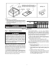
INSTALLATION
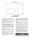
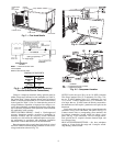
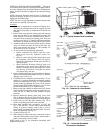
Unit is shipped in the vertical discharge configuration. To
convert to horizontal configuration, remove screws from side
duct opening covers and remove covers. Using the same
screws, install covers on vertical duct openings with the insula-
tion side down. Seals around duct openings must be tight. See
Fig. 1.
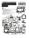
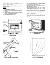
Step 1 — Provide Unit Support
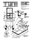
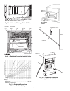
ROOF CURB — Assemble and install accessory roof curb in
accordance with instructions shipped with curb. See Fig. 2. In-
stall insulation, cant strips, roofing felt, and counter flashing as
shown.
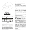
Ductwork must be attached to curb, not to the unit. The
accessory thru-the-bottom power and gas connection package
must be installed before the unit is set on the roof curb.
If field-
installed (thru-the-roof curb) gas connections are desired, use
factory-supplied
3
/
4
in. pipe coupling and gas plate assembly to
mount the thru-the-roof curb connection to the roof curb. Gas
connections and power connections to the unit must be field in-
stalled after the unit is installed on the roof curb.
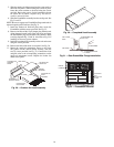
If electric and control wiring is to be routed through the
basepan, attach the accessory thru-the-bottom service connec-
tions to the basepan in accordance with the accessory installa-
tion instructions.
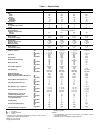
Ensure voltage listed on unit data plate agrees with electri-
cal supply provided for the unit.
Disconnect gas piping from unit when leak
testing at pressure greater than
1
/
2
psig. Pres-
sures greater than
1
/
2
psig will cause gas valve
damage resulting in hazardous condition. If
gas valve is subjected to pressure greater than
1
/
2
psig, it
must
be replaced before use. When
pressure testing field-supplied gas piping at
pressures of
1
/
2
psig or less, a unit connected to
such piping must be isolated by manually clos-
ing the gas valve.
Before performing service or maintenance operations on
unit, turn off main power switch to unit and install lockout
tag. Electrical shock could cause personal injury.
IMPORTANT: The gasketing of the unit to the roof curb
is critical for a watertight seal. Install gasket supplied
with the roof curb as shown in Fig. 2. Improperly
applied gasket can also result in air or water leaks and
poor unit performance.
48TJE,TJF004
48TJD,TJE,TJF005-007
Single-Package Rooftop Heating/Cooling Units