


40
SERVICE
Cleaning —
Inspect unit interior at the beginning of heat-
ing and cooling season and as operating conditions require.
EVAPORATOR COIL
1. Turn unit power off and tag disconnect. Remove evapora-
tor coil access panel.
2. If economizer is installed, remove economizer by discon-
necting 12-pin Molex plug and removing economizer
mounting screws. Refer to accessory economizer installa-
tion instructions or Optional Economizer sections on
pages 13 and 15 for more details.
3. Slide filters out of unit.
4. Clean coil using a commercial coil cleaner or dishwasher
detergent in a pressurized spray canister. Wash both sides
of coil and flush with clean water. For best results, back-
flush toward return-air section to remove foreign materi-
al. Flush condensate pan after completion.
5. Reinstall economizer and filters.
6. Reconnect wiring.
7. Replace access panels.
CONDENSER COIL — Inspect coil monthly. Clean con-
denser coil annually, and as required by location and outdoor
air conditions.
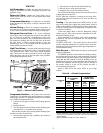
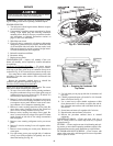
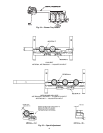
One-Row Coil Cleaning (Size 004)
— To access one-row
coils, remove screws securing condenser-fan grille to condens-
er fan top cover. Place grille on top of condenser fan top cover
as shown in Fig. 45. It is not necessary to remove the top cover.
Use a water hose or other suitable equipment to remove dirt
and debris. Clean the outer surfaces with a stiff brush in the
normal manner.
Reverse the procedure outlined above to reinstall the
condenser-fan grille and condenser fan top cover.
Two-Row Coil Cleaning (Sizes 005-007)
NOTE: Save all screws removed in this section. The screws
must be used when reinstalling the equipment.
1. To access 2-row coils, remove screws securing condenser-
fan grille to condenser coil top cover. Place grille on top of
condenser fan top cover as shown in Fig. 45 and 46. It is
not necessary to remove the top cover.
2. Remove 3 screws on right side of compressor access pan-
el. Remove one screw securing condenser coil top cover
to compressor access panel. Remove lower screws secur-
ing condenser coil to compressor mounting plate.
3. Remove 4 screws securing control box access panel. Re-
move three screws (located in front of the control box
access cover) securing condenser coil top cover.
4. Remove screws securing low-voltage access panel. Re-
move 2 screws inside low-voltage access panel. Tilt sheet
metal (located on left side of low-voltage connections)
back 45 degrees.
5. Remove screw securing refrigerant service port access
panel.
6. Remove 2 wire ties securing 2-row coils together at hair-
pin end.
7. Remove screws securing two corner posts. Remove two
corner posts.
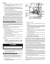
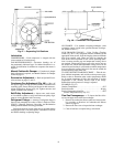
8. Use right corner post to prop up right side of condenser
coil top cover. Slide condenser coil partially out of con-
denser fan housing. See Fig. 46.
9. Use left corner post to prop up left side of condenser coil
top cover.
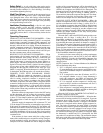
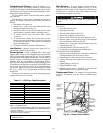
10. Carefully separate the outer coil section 3 to 4 in. from the
inner coil section. See Fig. 47.
11. Use a water hose or other suitable equipment to flush
down between the 2 coil sections to remove dirt and de-
bris. Clean the outer surfaces with a stiff brush in the nor-
mal manner.
12. Secure inner and outer coils together with 2 wire ties.
13. Reposition the outer and inner coil section.
14. Reverse the procedure outlined above to reinstall
equipment.
CONDENSATE DRAIN — Check and clean each year at
start of cooling season. In winter, keep drain dry or protect
against freeze-up.
FILTERS — Clean or replace at start of each heating and cool-
ing season, or more often if operating conditions require it. Re-
placement filters must be same dimensions as original filters.
OUTDOOR-AIR INLET SCREENS — Clean screens with
steam or hot water and a mild detergent. Do not use disposable
filters in place of screens.
When servicing unit, shut off all electrical power to unit to
avoid shock hazard or injury from rotating parts.
Fig. 45 — Coil Cleaning
Fig. 46 — Propping Up Condenser Coil
Top Cover