


16
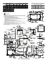
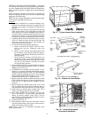
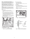
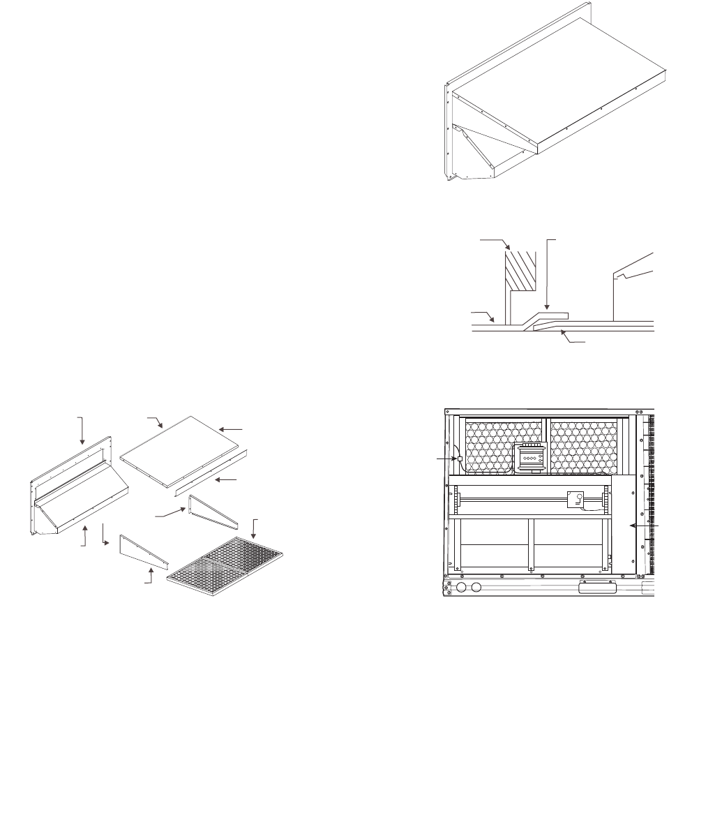
5. Slide the outdoor-air inlet screens into the screen track on
the hood side panels. While holding the screens in place,
fasten the screen retainer to the hood using the screws
provided. Repeat the process for the barometric exhaust
air screen.
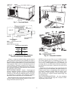
Do not attach completed (Fig. 30) hood as-
sembly to unit at this time.
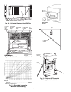
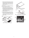
6. Slide the EconoMi$er assembly into the rooftop unit. See
Fig. 31 and 32.
NOTE: Be sure to engage rear EconoMi$er flange under tabs in
return-air opening of the unit base. See Fig. 31.
7. Install the outdoor-air block-off plate, then secure the
EconoMi$er with the screws provided. See Fig. 32.
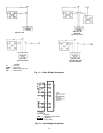
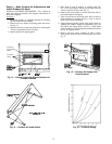
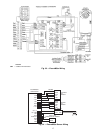
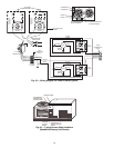
8. Remove and discard the 12-pin jumper plug from the unit
wiring harness located in the upper left corner and insert
the EconoMi$er plug into the unit wiring harness. Refer
to wiring diagrams Fig. 33 and 34. Also refer to Fig. 35 if
installing an accessory power exhaust.
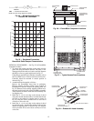
9. Install the complete hood assembly on the unit and secure
using the screws provided.
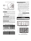
10. Remove the indoor fan motor access panel. See Fig. 36.
11. Mount the supply-air temperature sensor to the lower
left portion of the indoor blower housing with the
two (2) screws provided (see Fig. 37). Connect the violet
and pink wires to the corresponding connections on the
supply-air temperature sensor. Replace the indoor fan
motor access panel.
SEAL STRIP
SEAL STRIP
OUTDOOR AIR
HOOD TOP
SCREEN
RETAINER
OUTDOOR AIR
INLET
SCREENS
OUTDOOR AIR
HOOD SIDES
ASSEMBLED
EXHAUST HOOD
OUTDOOR AIR
OPENING
PANEL
Fig. 29 — Outdoor-Air Hood Assembly
WIRING
HARNESS
OUTDOOR
AIR
BLOCK-OFF
PLATE
Fig. 32 — EconoMi$er Installed
ECONOMI$ER
ECONOMI$ER REAR
FLANGE
UNIT BASE
UNIT FILTER
RACK
ECONOMI$ER CLIP
HVAC UNIT
Fig. 31 — Rear EconoMi$er Flange Installation
Fig. 30 — Completed Hood Assembly