


15
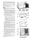
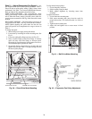
OPTIONAL ECONOMI$ER — See Fig. 26 for EconoMi$er
component locations.
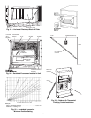
1. To remove the existing unit filter access panel, raise the
panel and swing the bottom outward. The panel is now
disengaged from the track and can be removed. Remove
the indoor coil access panel and discard. See Fig. 27.
If installing an optional Power Exhaust Assembly, refer to
the
EconoMi$er Power Exhaust Installation Instructions
.
Controller should be mounted in vertical position as
shown in Fig. 26.
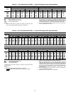
2. Assemble the hood assembly as follows:
Remove the EconoMi$er hood from its packaging.
Remove shipping brackets holding hood package to
EconoMi$er. Locate the outdoor-air opening panel. See
Fig. 28. Remove hood assembly shipping brackets locat-
ed on the back (sloped) side of the EconoMi$er assembly.
These brackets are used to retain the hood assembly dur-
ing shipping only.
3. Install the
1
/
8
x
3
/
4
-in. seal strip on the exhaust air hood
side panels and the bottom bracket. Assemble the exhaust
air hood to the outdoor-air opening panel as shown in
Fig. 28, using the screws provided.
Do not attach hood
assembly to unit at this time.
4. Install the
1
/
8
x
3
/
4
-in. seal strip on the outdoor-air hood
top and side panels. Assemble the outdoor-air hood to the
outdoor-air opening panel as shown in Fig. 29, using the
screws provided.
Do not attach hood assembly to the unit
at this time.
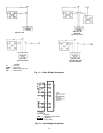
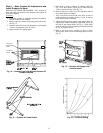
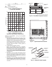
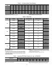
0.90
0.80
0.70
0.60
0.50
0.40
0.30
0.20
0.10
0.00
100
200 300 400
500 600
700
800
CFM
PRESSURE DROP (in. wg)
Fig. 25 — Durablade Economizer
Barometric Relief Damper Characteristics
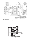
LEGEND
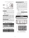
NOTE: See unit wiring diagram for details.
Fig. 24 — Wiring Connections for
Outdoor-Air Thermostat
OAT —
Outdoor-Air Thermostat
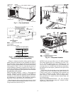
OUTDOOR AIR
OPENING PANEL
SEAL STRIP
EXHAUST AIR SCREEN
EXHAUST AIR
HOOD TOP
SCREEN
RETAINER
EXHAUST AIR
HOOD SIDES
EXHAUST AIR
BOTTOM BRACKET
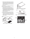
Fig. 28 — Exhaust Air Hood Assembly
OUTDOOR-AIR
OPENING PANEL
FILTER ACCESS
PANEL
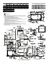
Fig. 27 — Typical Access Panel Locations
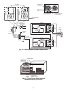
BAROMETRIC RELIEF DAMPERS
CONTROLLER
ECONOMI$ER
PLUG
GEAR-DRIVEN
DAMPER
OUTDOOR AIR
TEMPERATURE
SENSOR
ACTUATOR
Fig. 26 — EconoMi$er Component Locations