


16
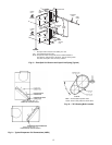
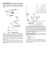
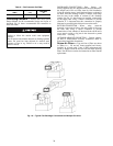
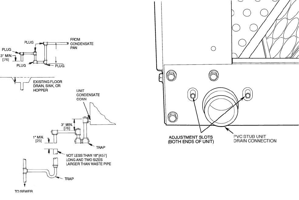
Condensate Drain — Install a trapped condensate drain
line to unit connection as shown in Fig. 12. The unit drain con-
nection is a PVC stub. See Fig. 13. Some areas may require an
adapter to connect to either galvanized steel or copper pipe.
For these applications, install a field-supplied threaded PVC
adapter.
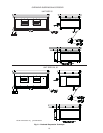
Fig. 12 — Condensate Drains
NOTE: A trap must be installed in the condensate drain
line to ensure that the static pressure of fans is balanced
with the water column in the drain line and that condensate
can drain completely from pan. Without a trap, air can be
drawn up drain line until water level in condensate pan
becomes equal to static pressure created by fans, preventing
complete drainage. Conditions will worsen as filters
become dirty.
Install clean-out plugs in trap. Pitch drain line downward to an
open floor drain or sump. Provide service clearance around
drain line to permit removal of unit panels. Observe all local
sanitary codes.
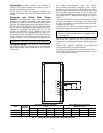
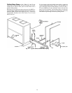
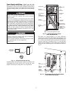
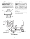
Fig. 13 — Drain Pan Slope Adjustment
As shipped, the unit’s condensate drain pan is NOT sloped to-
wards the drain connection. The pan slope must be changed to
pitch towards the side of the unit with the drain connection. See
Fig. 13. Loosen the 2 screws next to the drain outlet at both
ends of the unit, push drain pan down in the slots near the drain
connection, and up in the slots on the opposite end. Retighten
screws. The pan should have a pitch of at least
1
/
4
-in. over its
length toward the drain connection.
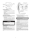
Fan Motors and Drives — Motor and drive packages
are factory installed in all units. The motor and drive packages
consist of the following items:
1 — fan motor
1 — adjustable motor pulley
1 — fan pulley
2 — matched fan belts (40RUA*25-30, 40RUS*25-30 units)
For instructions on changing fan rotation, changing drive
speeds and adjusting drives, see Pulley and Drive Adjustment
in the Service section.
3” MIN.
[76]
NOTE: Dimensions in [ ] are in millimeters