


2
PRE-INSTALLATION
1. The power supply (v, ph, and Hz) must correspond to that
specified on unit rating plate.
2. The electrical supply provided by the utility must be suf-
ficient to handle load imposed by this unit.
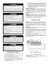
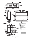
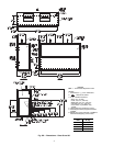
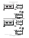
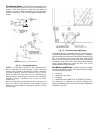
3. Refer to Installation, General section (page 2) and
Fig. 2A and Fig. 2B for locations of electrical inlets, con-
densate drain, duct connections, and required clearances
before setting unit in place.
4. This installation must conform with local building codes
and with the NEC (National Electrical Code) or ANSI
(American National Standards Institute)/NFPA (National
Fire Protection Association) latest revision. Refer to
provincial and local plumbing or wastewater codes and
other applicable local codes.
Moving and Storage — To transfer unit from truck to
storage site, use a fork truck. Do not stack units more than
2 high during storage. If unit is to be stored for more than
2 weeks before installation, choose a level, dry storage site free
from vibration. Do not remove plastic wrap or skid from unit
until final installation.
Rigging — All 40RU Series units can be rigged by using
the shipping skid. Units are shipped fully assembled. Do not
remove shipping skids or protective covering until unit is ready
for final placement; damage to bottom panels can result. Use
slings and spreader bars as applicable to lift unit.
INSTALLATION
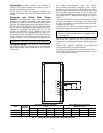
General — Allow 2
1
/
2
ft at front and side of unit for service
clearance and airflow. For units equipped with an economizer,
refer to the accessory installation instructions for additional
clearance requirements. Be sure floor, wall, or ceiling can
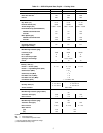
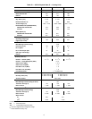
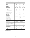
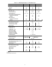
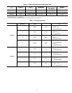
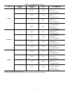
support unit weight (Tables 1A – 1D). See Fig. 2A and Fig. 2B
for dimensions.
Uncrating — Move unit as near as possible to final loca-
tion before removing shipping skid.
Remove metal banding, top skid, and plastic wrap. Examine
unit for shipping damage. If shipping damage is evident, file
claim with transportation agency. Remove base skid just prior
to actual installation.
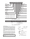
Check nameplate information against available power supply
and model number description in Fig. 3.
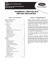
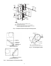
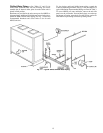
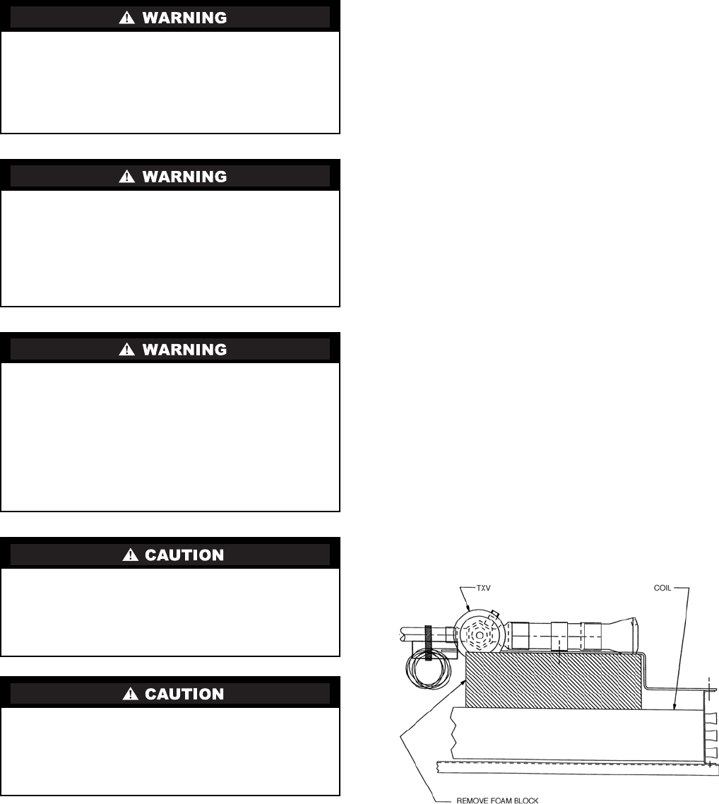
NOTE: Be sure to remove the styrofoam shipping pad from
the thermostatic expansion valve (TXV). Verify that it has
been removed. See Fig. 1.
Fig. 1 — Foam Block Location
Accessories — Refer to instructions shipped with each
accessory for specific information.
ELECTRICAL SHOCK HAZARD
Failure to follow this warning could cause personal injury
or death.
Before performing service or maintenance operations on
unit, always turn off main power switch to unit and install
lockout tag. Unit may have more than one power switch.
UNIT OPERATION AND SAFETY HAZARD
Failure to follow this warning could cause personal injury,
death and/or equipment damage.
Puron® (R-410A) refrigerant systems operate at higher
pressures than standard R-22 systems. Do not use R-22
service equipment or components on Puron refrigerant
equipment.
PERSONAL INJURY AND ENVIRONMENTAL
HAZARD
Failure to follow this warning could cause personal injury
or death.
Relieve pressure and recover all refrigerant before system
repair or final unit disposal.
Wear safety glasses and gloves when handling refrigerants.
Keep torches and other ignition sources away from
refrigerants and oils.
CUT HAZARD
Failure to follow this caution may result in personal injury.
Sheet metal parts may have sharp edges or burrs. Use care
and wear appropriate protective clothing, safety glasses and
gloves when handling parts and servicing 40RU units.
UNIT OPERATION HAZARD
Failure to follow this caution could cause equipment
damage.
Ensure voltage listed on unit data plate agrees with
electrical supply provided for the unit.
LEGEND
TXV — Thermostatic Expansion Valve