


20
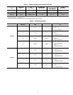
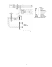
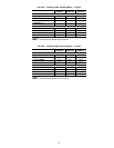
Table 6 — Fan Contactor Coil Data
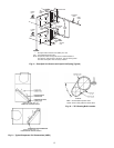
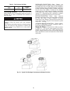
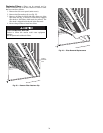
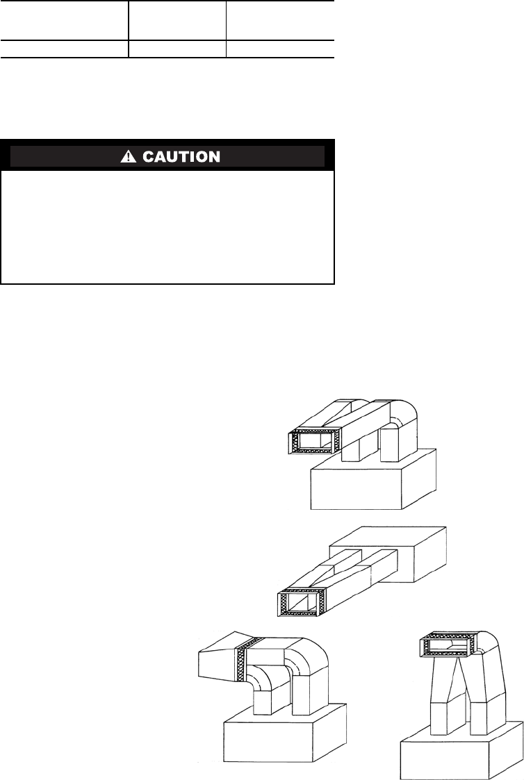
Connecting Ductwork — Refer to the Carrier System
Design Manual for the recommended design and layout of
ductwork. Fig. 18 shows recommended duct connection to
units with 2 fans.
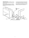
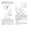
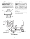
DISCHARGE CONNECTIONS — Duct flanges are
factory-supplied; they are shipped inside the unit attached to
the hairpin end of the coil tube sheet for field installation.
Using the existing screws, install the duct flanges on the unit’s
fan deck. Each fan discharge requires 2 flanges; each flange
must be bent in the middle to conform to the discharge
opening. See Fig. 19. After flanges are installed, connect them
to the supply duct using a canvas connection to prevent
vibration. It is important that this connection be properly
fabricated to prevent high air friction losses and air noise.
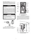
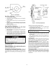
RETURN CONNECTION — When using return-air
ductwork, route return-air duct to the unit’s return air inlet near
the filter rack, using a canvas connection to prevent
transmission of unit vibration. If the duct blocks off the unit’s
access panel, provide a slip joint in the ductwork to permit
removal for servicing.
OUTDOOR-AIR INLET CONNECTION — Connect outdoor-
air inlet to field-installed accessory economizer. Refer to
Economizer Installation Instructions.
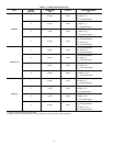
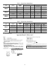
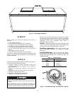
Return-Air Filters — Type and size of filters are shown
in Tables 1A – 1D and are factory-supplied and factory-
installed. In all units with 2 fans, a filter replacement tool
(hook) is shipped inside the unit for field use when replacing
filters. See the Service section for instructions on filter element
replacement.
Fig. 18 — Typical Fan Discharge Connections for Multiple Fan Units
UNIT
40RU**
VOLTAGE
(vac)
MAXIMUM
HOLDING
VA
25, 28, 30 24 10
UNIT OPERATION HAZARD
Failure to follow this caution could cause equipment
damage.
Do not operate unit without ductwork or discharge plenum
unless fan speed has been adjusted for external static
pressure of zero in. wg. Failure to do so may result in
motor overload.