


11
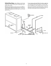
Unit Isolation — Where extremely quiet operation is
essential, install isolators between floor and base of unit, or
between ceiling and top section of unit.
Be sure that unit is level and adequately supported. Use
channels at front and sides of unit for reference points when
leveling.
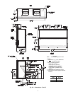
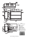
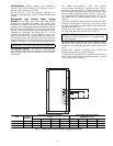
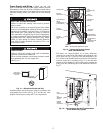
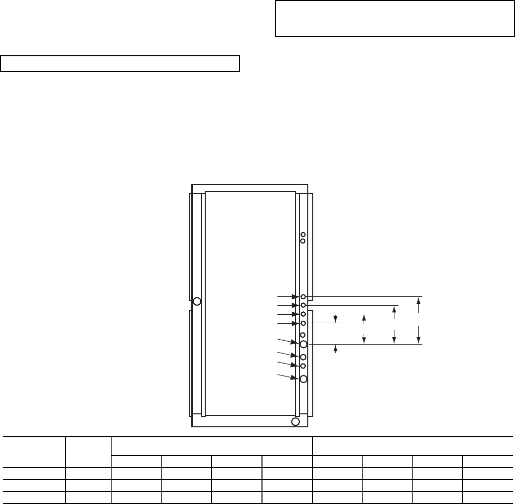
Refrigerant and Chilled Water Piping
Access —
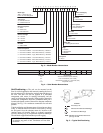
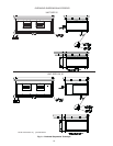
The 40RU Series units come with standard
knockouts for refrigerant and chilled water piping. These
knockouts are located on both sides of the unit for installation
flexibility. The standard knockouts provide sufficient access to
the unit’s coils for all 40RUA*25, 28, and 30 units. RUS*25,
28, and 30 units require additional holes which must be field-
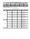
fabracated to accomodiate the piping. See Fig. 7 for the
positions and dimensions of the additional access holes
required for the RUS units. Recommended access hole use is
also listed for all units. Note that Fig. 7 shows the access holes
on the control-box side of the unit; this is the side of the unit
with the coil headers, so it is used most often for piping access.
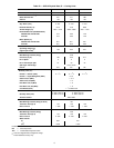
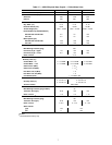
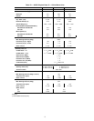
Refrigerant Piping — See Tables 1A–1D for refrigerant
pipe connection sizes. For ease in brazing, it is recommended
that all internal solder joints be made before unit is placed in
final position.
The 40RU direct-expansion units have internal
factory-installed thermostatic expansion valves (TXVs),
distributors, and nozzles for use with R-410A. See Table 2
for part numbers. Knockouts are provided in the unit corner
posts for 40RU refrigerant piping. See Fig. 7, which also
lists recommended knockouts and access holes to use for
each 40RU unit size. Recommended fittings are listed in
Table 3.
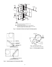
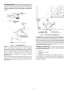
The sensor bulb capillary tubes must be routed from the TXVs
inside the unit through one of the piping access holes. Clamp
the TXV sensor bulb on a vertical portion of the suction line,
outside the unit. See Fig. 8.
NOTE: Be sure to remove the styrofoam shipping pad from
the TXV. Verify that it has been removed. See Fig. 1.
The 40RU Series evaporator coils have a face-split design.
Ensure that lower circuit of coil is first on/last off when
connected to the condensing unit and/or system controls. See
Fig. 9.
External TXV equalizer connections are provided and
factory-brazed into the coil suction manifolds.
If suction line must be horizontal, clamp bulb to suction line at
least 45 degrees above bottom, at approximately the 4 o’clock
or 8 o’clock position. See Fig.10.
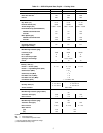
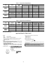
Fig. 7 — Refrigerant and Chilled Water Piping Access Holes
IMPORTANT: Do not bury refrigerant piping underground.
IMPORTANT: Never attach the sensor to the suction
manifold. Do NOT mount the sensor on a trapped portion
of the suction line.
4
3
2
1
7
6
5
A
B
C
D
8
UNIT
USE HOLE
NUMBERS
FIELD-FABRICATED HOLE DIAMETERS
in. (mm)
FIELD-FABRICATED HOLE POSITION
DIMENSIONS, in. (mm)
No. 5No. 6No. 7No.8ABCD
40RUA*25, 28, 30 1, 2, 3, 4————————
40RUS*25 4, 5, 6, 7 1
3
/
4
(44.5) 1
3
/
4
(44.5) 1
3
/
4
(44.5) — 3.0 (76.2) 6.0 (152.5) 10.5 (266.7)
40RUS*28, 30 5, 6, 7, 8 2
1
/
2
(63.5) 2
1
/
2
(63.5) 2
1
/
2
(63.5) 2
1
/
2
(63.5) 6.0 (152.5) 9.625 244.5) 13.38 (339.9) 17.0 (431.8)