


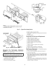
Evaporator-Fan Motor Replacement
1. Shut off unit power supply.
2. Remove upper outside panel and open hinged door to
gain access to motor.
3. Fully retract motor plate adjusting bolts.
4. Loosen the two rear (nearest the evaporator coil) motor
plate nuts.
5. Remove the two front motor plate nuts and carriage bolts.
6. Slide motor plate to the rear (toward the coil) and re-
move fan belt(s).
7. Slide motor plate to the front and hand tighten one of
the rear motor plate nuts (tight enough to prevent the
motor plate from sliding back but loose enough to allow
the plate to pivot upward).
8. Pivot the front of the motor plate upward enough to al-
low access to the motor mounting hex bolts and secure
in place by inserting a prop.
9. Remove the nuts from the motor mounting hex bolts and
remove motor.
10. Reverse above steps to install new motor.
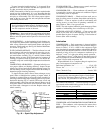
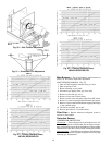
Condenser-Fan Adjustment
1. Shut off unit power supply.
2. Remove fan guard.
3. Loosen fan hub setscrews.
4. Adjust fan height on shaft using a straightedge placedacross
venturi and measure per Fig. 51.
5. Fill hub recess with permagum if rubber hubcap is
missing.
6. Tighten setscrews and replace panel(s).
7. Turn on unit power.
Power Failure — The economizer damper motor is a
spring return design. In event of power failure, dampers will
return to fully closed position until power is restored.
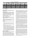
Refrigerant Charge — Amount of refrigerant charge
is listed on unit nameplate and in Table 1. Refer to Carrier
GTAC II; Module 5; Charging, Recovery, Recycling, and
Reclamation section for charging methods and procedures.
Unit panels must be in place when unit is operating dur-
ing charging procedure.
NOTE: Do not use recycled refrigerant as it may contain
contaminants.
NO CHARGE — Use standard evacuating techniques.After
evacuating system, weigh in the specified amount of
refrigerant (refer to Table 1).
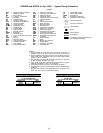
LOW CHARGE COOLING — Using appropriate cooling
charging chart (see Fig. 52 and 53), add or remove refrig-
erant until conditions of the appropriate chart are met. Note
that charging chart is different from those normally used.An
accurate pressure gage and temperature sensing device are
required. Measure liquid line pressure at the liquid line serv-
ice valve using pressure gage. Connect temperature sensing
device to the liquid line near the liquid line service valve
and insulate it so that outdoor ambient temperature does not
affect reading.
Using the above temperature and pressure readings, find
the intersect point on the appropriate cooling charging chart.
If intersection point on chart is above line, add refrigerant.
If intersection point on chart is below line, carefully reclaim
some of the charge. Recheck suction pressure as charge is
adjusted.
NOTE: Indoor-air cfm must be within normal operating range
of unit. All outdoor fans must be operating.
Thermostatic Expansion Valve (TXV) — Each cir-
cuit has a TXV. The TXV is nonadjustable and is factory set
to maintain 10 to 13° F superheat leaving the evaporator coil.
The TXV controls flow of liquid refrigerant to the evapo-
rator coils.
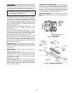
Gas Valve Adjustment
NATURAL GAS — The 2-stage gas valve opens and closes
in response to the thermostat or limit control.
When power is supplied to valve terminals 3 and 4, the
pilot valve opens to the preset position. When power is sup-
plied to terminals 1 and 2, the main valve opens to its preset
position.
The regular factory setting is stamped on the valve body
(3.5 in. wg).
To adjust regulator:
1. Set thermostat at setting for no call for heat.
2. Turn main gas valve to OFF position.
3. Remove
1
⁄
8
-in. pipe plug from manifold. Install a water
manometer pressure-measuring device.
4. Set main gas valve to ON position.
5. Set thermostat at setting to call for heat.
6. Remove screw cap covering regulator adjustment screw
(See Fig. 54).
7. Turn adjustment screw clockwise to increase pressure or
counterclockwise to decrease pressure.
8. Once desired pressure is established, set thermostat set-
ting for no call for heat, turn off main gas valve, remove
pressure-measuring device and replace
1
⁄
8
-in. pipe plug
and screw cap.
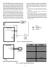
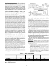
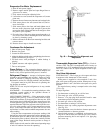
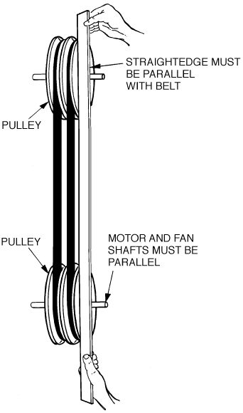
Fig. 49 — Evaporator-Fan Alignment and
Adjustment
47