


Space Temperature Reset Example — The occupied cooling
set point is set to 73 F. The Reset Ratio is set to 5. The Reset
Limit is set to 20° F. The Reset Ratio determines how many
degrees F the temperature is reset. At 72 F, the supply tem-
perature will be reset 5 degrees higher. At 71 F, the supply
temperature will be reset 10 degrees higher. At 70 F, the sup-
ply temperature will be reset 15 degrees higher. At 69 F, the
supply temperature will be reset 20 degrees higher and the
Reset Limit will have been reached.
SUPPLYAIR TEMPERATURE RESET — Supply air tem-
perature reset is used to reset the supply air temperature util-
ity. A 4 to 20 mA signal (field-supplied) is required. The re-
set option does not require enabling.
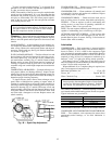
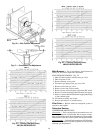
POWER EXHAUST OPERATION — The optional power
exhaust packages are factory- or field-installed with vertical
units and optionally installed in the return air ductwork for
horizontal applications. The standard (offered with constant
volume or variableair volume units) and the modulating power
exhaust (offered on VAV units) are the two packages offered.
The modulating power exhaust package is equipped with a
field-adjustable static pressure controller to stage up to 4 power
exhaust stages which will maintain a building static pres-
sure. The blue controller located in the control box below
the control board can be adjusted, by removing the covers
and adjusting the set point dial to the desired building pres-
sure. The blue controller monitors the 4 individual sequenc-
ers which activate the 4 individual power exhaust motors.
The standard power exhaust package controls up to 2 stages
of power exhaust to maintain building pressure. The power
exhaust package can be configured to deliver positive or nega-
tive building pressure. These power exhaust stages are staged
according to a percentage of the economizer dampers
position. Default values are 25% for Stage 1 and 75% for
Stage 2. This package has set points that are adjustable
through software (Service Tool, Building Supervisor, or
ComfortWorks™).
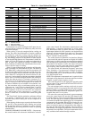
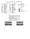
SMOKE CONTROL MODES — The 48EJ,EK,EW,EYunits
with an optional expansion board perform fire and smoke
control modes.The expansion board provides 4 modes which
can be used to control smoke within the conditioned area.
The modes of operation are fire shutdown, pressurization,
evacuation, and smoke purge. See Table 19.
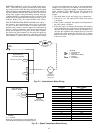
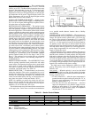
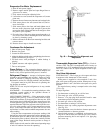
SMOKE DETECTOR — A smoke detector can be used to
initiate fire shutdown. This can be accomplished by a set of
normally closed pilot relay contacts which will interrupt power
from the 24-v transformer, secondary ‘‘B’’ terminal to the
control circuit breaker (CB4). See Fig. 44. The wire that con-
nects these two points is white and labeled ‘‘W78.’’
NOTE: On standard gas models, the indoor fan will con-
tinue to run 45 seconds after the call for heat has been ter-
minated. If fire shutdown is initiated the fan will stop im-
mediately. No 45-second delay will occur.
The smoke detector may be mounted in the return air duct
or the supply duct. Carrier does not make recommendations
as to specific smoke detector location due to liability
considerations.
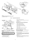
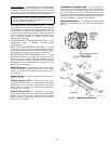
INDOOR AIR QUALITY CONTROL — The accessory ex-
pansion board and accessory IAQ sensor are required for IAQ
control. The Carrier sensors operate witha4to20mAsig-
nal. The 4 to 20 mA signal is connected to T11 (+) and T12
(−) on the expansion board for the IAQ sensor, and T13 (+)
and T14 (−) on the expansion board for the OAQ (Outdoor
Air Quality) sensor. The sensor is field-mounted and wired
to the expansion board installed in the unit main control box.
The IAQ sensor must be powered by a field-supplied 24-v
power supply (ungrounded). Do not use the unit 24-v power
supply to power the sensor.
Once installed, the sensor must be enabled. The sensor is
configured with default values which may be changed through
network access software. To work properly, the IAQ sensor
high and low reference points for the sensor that is used must
match the configured values. The expansion board reacts to
a 4 to 20 mA signal from the IAQ sensor. The low reference
(4 mAoutput) must be configured to the minimum IAQ sen-
sor reading.The high reference (20 mA output) must be con-
figured to the maximum IAQ sensor reading.
The IAQ sensor can be configured to either low or high
priority. The priority value can be changed by the user. The
default is low.
Low priority — When the priority is set to low, the initial
control is to the IAQ set point, but the outside air damper
position will change to its minimum position when the fol-
lowing conditions occur:
• CV units with sensor — when the space temperature is
greater than the occupied cooling set point plus 2° F or
when the space temperature is less than the occupied
heating set point minus 2° F.
• VAV units and CV units with thermostat — when the
supply-air temperature is less than the supply-air tem-
perature set point minus 8° F or when the supply-air
temperature is greater than the supply air temperature
set point plus 5° F for 4 minutes.
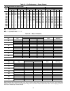
Table 19 — Smoke Control Modes
DEVICE PRESSURIZATION SMOKE PURGE EVACUATION FIRE SHUTDOWN
Economizer 100% 100% 100% 0%
Indoor Fan/VFD ON ON OFF OFF
Power Exhaust (all outputs) OFF ON ON OFF
Heat Stages OFF OFF OFF OFF
HIR ON ON OFF OFF
LEGEND
HIR — Heat Interlock Relay
VFD — Variable Frequency Drive
Fig. 44 — Field-Supplied Smoke Detector Wiring
43