


Step 11 — Install All Accessories — After all the
factory-installed options have been adjusted, install all field-
installed accessories. Refer to the accessory installation in-
structions included with each accessory.
MOTORMASTER III INSTALLATION
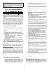
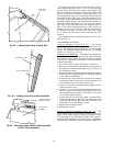
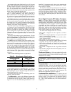
Install Field-Fabricated Wind Baffles — Wind baffles must
be field-fabricated for all units to ensure proper cooling cycle
operation at low-ambient temperatures. See Fig. 39 for baffle
details. Use 20-gage, galvanized sheet metal, or similar
corrosion-resistant metal for baffles. Use field-supplied screws
to attach baffles to unit. Screws should be
1
⁄
4
-in. diameter
and
5
⁄
8
-in. long. Holes for wind baffles are pre-punched in
the unit sheet metal.
To avoid damage to the refrigerant coils and electrical
components, use recommended screw sizes only.
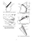
On 48EJ,EK,EW,EY024-034 units, the wind baffles at-
tach to flanges formed on the outer sheet metal of the unit
where the condenser coil tube sheets attach.
On 48EJ,EK,EW,EY038-048 units, the wind baffles at-
tach to flanges formed on the outer sheet metal of the unit
corner post. The other end of the baffle is attached to the
center panel between the condenser coil and the indoor sec-
tion. Two baffles are required for 48EJ,EK,EW,EY038-048
units.
Install Motormaster III Controls — Only one Motormaster
III control is required per unit.
Motor — The circuit no. 1 (lead compressor) outdoor-fan
motor (OFM) will need to be changed out in the field to ac-
commodate the Motormaster III accessory. The replacement
motor part no. is HD52AK652.
On 48EJ,EK,EW,EY038-048 units, only one OFM will need
to be changed out. The no. 1 compressor is located at the left
side of the unit looking from the compressor end. The circuit
no. 2 OFMs are controlled to shut off at 55 F and turn on at
65 F outdoor-air temperature.
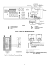
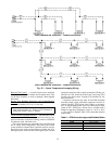
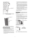
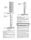
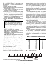
Sensor — Install the sensor for thermistor input control in
the location shown in Fig. 40A-C. Connect sensor leads to
the violet and gray control signal leads on the Motormaster
III control.
Signal Selection Switch — Remove the cover of the Motor-
master III control. Set the switch to accept the thermistor
sensor input signal. Set the frequency to match the unit power
supply (60 Hz).
Motormaster III Control — The recommended mounting lo-
cation is in the indoor fan section, mounted on the panel that
separates the indoor and outdoor sections. On VAV units,
this location is next to the VFD.
Do not route the Motormaster III wiring next to the VFD
on VAV units. Use a separate connector through the partition
when wiring to the OFM.
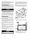
Electrical Connections
To avoid possibility of electrical shock and personal in-
jury, turn off all power to unit before making electrical
connections.
When replacing the OFM, reconnect the black, yellow, and
blue wires form the outdoor fan contactor to the black, yel-
low, and blue wires of the Motormaster III control. Run new
wires from the red, orange, and brown wires to the leads of
the new OFM. Connect the green wire from the control to
ground.
NOTE: On all 575-v units, 2 transformers (part no.
HT01AH851) must be used for each Motormaster III con-
trol to lower the supply voltage to the control to 460-v. Trans-
formers can be mounted anywhere outside the control box.
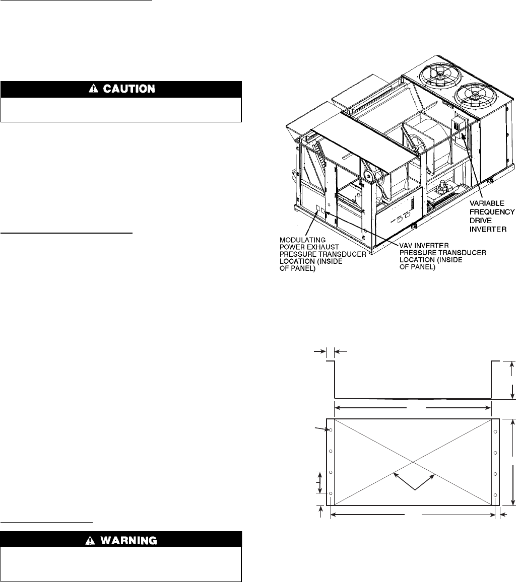
VAV — Variable Air Volume
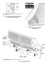
Fig. 38 — Pressure Transducer Locations
18
77.7
1
BOTH SIDES
CROSS-BREAK
78.7
0.5
61
4.62
17.167
BETWEEN
HOLES
(TYPICAL)
0.312 DIA
HOLES
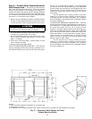
NOTE: All dimensions are in inches. Material: 20 gage galvanized
steel or other non-corrosive material.
Fig. 39 — Motormaster III Baffle Details
30