


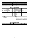
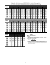
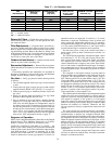
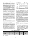
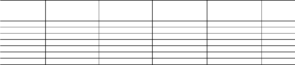
Table 17 — Air Quantity Limits
UNIT
48EJ,EK,EW,EY
MINIMUM HEATING
AIRFLOW
(Low Heat)
MINIMUM HEATING
AIRFLOW
(High Heat)
MINIMUM COOLING
AIRFLOW (VAV)
AT FULL LOAD
OPERATION
MINIMUM COOLING
AIRFLOW (CV)
MAXIMUM
AIRFLOW
024 5730 5950 2000 6,000 10,000
028 5730 5950 2500 7,500 12,500
030 5730 5950 2750 8,250 13,750
034 5730 5950 3000 9,000 15,000
038 7360 9820 3500 10,500 17,500
044 7360 9820 4000 12,000 20,000
048 7360 9820 4500 13,500 22,500
LEGEND
CV — Constant Volume
VAV — Variable Air Volume
Return-Air Filters — Check that correct filters are in-
stalled in filter tracks (see Table 1). Do not operate unit with-
out return-air filters.
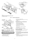
Filter Replacement — To replace filters, open filter ac-
cess door (marked with label). Remove inner access panel.
Remove plastic filter retainer in between filter tracks by slid-
ing and pulling outward. Remove first filter by sliding it out
of the opening in filter track. Locate filter removal tool, which
is shipped next to the return air dampers. Use the filter re-
moval tool to remove the rest of the filters.
Outdoor-Air Inlet Screens — Outdoor-air inlet screens
must be in place before operating unit.
Economizer Adjustment — Remove filter access panel.
Check that outdoor-air damper is closed and return-air damper
is open.
Economizer operation and adjustment are described in
Sequence of Operation section on this page; and Minimum
Damper Position Setting section on page 24.
Gas Heat — Verify gas pressures before turning on heat
as follows:
1. Turn off field-supplied manual gas stop, located external
to unit.
2. Connect pressure gage to supply gas tap, located on field-
supplied manual shutoff valve (see Fig. 13 on page 13).
3. Connect pressure gage to manifold pressure tap on unit
gas valve.
4. Supply gas pressure must not exceed 13.5 in. wg. Check
pressure at field-supplied shut-off valve.
5. Turn on manual gas stop and initiate a heating demand.
Jumper R to W1 in the control box to initiate heat. On
VAV units, the RAT (Return-Air Temperature) must be
less than or equal to 68 F for heating to be energized. Use
the field test procedure to verify heat operation. After the
unit has run for several minutes, verify that incoming pres-
sure is 5.0 in. wg or greater, and that the manifold pres-
sure is 3.5 in. wg. If manifold pressure must be adjusted,
refer to Gas Valve Adjustment section on page 47.
Sequence of Operation
NOTE: Unit is shipped with default values that can be changed
through Service Tool, Building Supervisor, or Comfort-
Works™ software. See Table 18 for default values.
COOLING, CONSTANT VOLUME (CV) UNITS — On
power up, the control module will activate the initialization
software of the control board. The initialization software then-
reads DIP switch no. 1 position to determine CV or VAV
operation. Next, DIP switch no. 2 is read to determine if the
control is thermostat or sensor type operation. If switch 2 is
open,then sensors are employed. If switch no. 2 is closed,
thermostat is employed. Initialization clears all alarms and
alerts, remaps the input/output database for CV operation,
sets maximum heat stages to 2, and sets maximum cool stages
to 3. The control reads DIP switch no. 3 and if open, then it
sets the internal flag for expansion mode operation.
The first time power is sent to the control board after a
power outage, power up takes 5 minutes plus a random 1 to
63 seconds.
The TSTAT function performs a thermostat based control
by monitoring Y1, Y2, W1, W2, and G inputs. These func-
tions control stages cool1, cool2, heat1, heat2, and indoor
fan, respectively. If TSTAT function is NOT selected, the
control determines the occupancy state on the Time Sched-
ules or with remote occupied/unoccupied input. If tempera-
ture compensated start is active, the unit will be controlled
as in the Occupied mode. User-defined set points are shown
in Table 18.
The occupied or unoccupied comfort set points must be
selected and the space temperature offset input will be used,
if present. The Occupied Heat set point default value is
68 F. The Occupied Cool set point default value is 78 F. The
Unoccupied Heat set point default value is 55 F. The Un-
occupied Cool set point value is 90 F. The control board will
set appropriate operating mode and fan control. The control
board will turn on indoor fan, if in Occupied mode, or de-
termine if unit is in Unoccupied mode and the space tem-
perature is outside of the unoccupied comfort set points,
(Unoccupied Heat or Unoccupied Cool).
The control board will then monitor space temperatureagainst
comfort set points and control heating or cooling stages as
required. If system is in the Occupied mode, the economizer
will operate as required. If the system is in Unoccupied
mode, the system will perform nighttime free cool and IAQ
(indoor air quality) pre-occupancy purge as required (when
functions are enabled via software). Whenever the DX
(di-rect expansion) cooling is requested, the outdoor fan will
operate.
The control board will operate economizer, run diagnos-
tics to monitor alarms/alerts at all times, and respond to CCN
communications to perform any configured network POC
(product outboard control) functions such as timeand outdoor-
air temperature broadcast and Global occupancy broadcast.
When the optional expansion I/O board is employed, it will:
perform periodic scan and maintain database of expanded
I/O points, perform Fire/Smoke control (power exhaust re-
quired); and if in Occupied mode perform IAQ control and
monitor fan, filter, demand limit, and field-applied status (with
accessories).
If thermostats are used to energize the G input, the control
will turn on indoor fan without delay and open economizer
dampers to minimum position.
39