


IMPORTANT: When connecting the CCN communi-
cation bus to a system element, use a color coding sys-
tem for the entire network to simplify installation and
checkout. See Table 6.
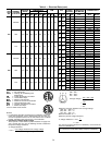
Table 6 — Color Code Recommendations
SIGNAL
TYPE
CCN BUS CONDUCTOR
INSULATION COLOR
CCN PLUG
PIN NO.
Positive (+) RED 1
Ground WHITE 2
Negative (−) BLACK 3
NOTE: If a cable with a different color scheme is selected,
a similar color code should be adopted for the entire
network.
At each system element, the shields of the communica-
tion bus cables must be tied together. If the communication
bus is entirely within one building, the resulting continuous
shield must be connected to a ground at one point only.If
the communication bus cable exits from one building and
enters another, the shields must be connected to grounds at
the lightning suppressor in each building where the cable
enters or exits the building (one point per building only).
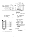
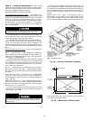
To connect the unit to the network:
1. Turn off power to the control box.
2. Cut the CCN wire and strip the ends of the red (+), white
(ground), and black (−) conductors. (If a different net-
work color scheme is used, substitute appropriate
colors.)
3. Remove the 3-pin male plug from the base module in the
main control box, and connect the wires as follows:
a. Insert and secure the red (+) wire to terminal 1 of the
3-pin plug.
b. Insert and secure the white (ground) wire to
terminal 2 of the 3-pin plug.
c. Insert and secure the black (−) wire to terminal 3 of
the 3-pin plug.
4. Insert the plug into the existing 3-pin mating connector
on the base module in the main control box.
Step 9 — Make Outdoor-Air Inlet Adjustments
ECONOMIZER
NOTE: If accessory power exhaust or barometric relief pack-
ages are being added to the unit, install power exhaust or
barometric relief before installing economizer hoods.
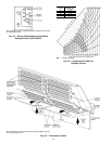
Economizer Hood Assembly — The economizer hood is
shipped in a package secured to the outside of the unit and
must be field-assembled. There are 2 hoods on every unit.
The 48EW/EY units are side supply and side return. The re-
turn duct limits access to economizer filters from below.
Filter tracks (mounting angle without tabs) must be installed
correctly to allow access to economizer filters from each side.
Perform the following procedure to assemble the econo-
mizer hood:
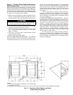
NOTE: Before assembly of the economizer hood, check along
the outer edges of the economizer assembly for any seal strip
protruding past the flanges. Trim the excess seal strip so that
it is flush with the economizer assembly flanges.
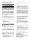
1. Apply black seal strip (provided in package) to outside
top-edge of hood sides. Wrap seal strip over edge to cover
top flange (4 hood sides). Make sure seal strip covers
screw holes. Allow strip to overhang
1
⁄
8
-in. past the end
opposite the mounting flange. See Fig. 23.
2. Assemble hood sides, top, and cross member with gas-
keted screws provided. See Fig. 24.
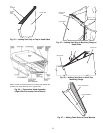
3. Attach 10 green speed clips (provided) to hood top.
4. Apply black seal strip (provided) to mounting flanges of
hood sides being sure to cover mounting holes. See
Fig. 25.
NOTE: Each hood assembly has a slotted side that should
be adjacent to the other hood when mounted to the unit.
5. Apply black seal strip (provided) to hood top mounting
flange. Seal strip of hood top mounting flange must press
tightly against seal strip of hood side mounting flanges.
See Fig. 26.
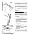
6. Add gray foam strip (provided in package) to cross mem-
bers on bottom tray. See Fig. 27.
7. Place gray foam strip (provided) on inside of slotted hood
side between filter and cross member opposite the mount-
ing end. See Fig. 28.
8. Attach gray foam strip (provided) to block-off baffle on
outer face of flange. See Fig. 29.
9. Remove the screws on each end and along top of damper
assembly of unit. Remove top 2 screws on each side of
filter panel under damper assembly. Set hood assembly
in place and attach to unit using these screws.
10. Attach accessory enthalpy bracket on hood side furthest
from control box end. Locate bracket on inside upper
right-hand corner of economizer hood using hood mount-
ing holes. Mount outdoor-air thermistor to enthalpybracket
(if purchased).Attach and wire enthalpy assembly. Place
quick connects on enthalpy wires.
11. Remove screws along bottom of damper assembly. Lo-
cate and mount blockoff baffle using these screws.
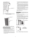
12. Assemble 2 filter tracks side-by-side with the as-
sembled ends together.
13. Attach mounting angle (without tabs) to the assembled
end of the filter track. See Fig. 30.
14. Attach 6 green speed clips (provided) to mounting angles.
Engagement section of clip faces inside of rack.
15. Attach remaining mounting angle (with tabs) to other
end of the filter track with no. 10 screws provided. See
Fig. 31.
16. Place filter track assembly in bottom of hood by placing
tabbed end into slotted side (with tab on bottom) and
attaching opposite end to hood with speed clips and gas-
keted screws provided. Tabs can be hand bent after they
have been inserted into the side.
NOTE: The filter track assembly end with screws should
face away from the other hood when mounted on the
unit.
NOTE: Tabs from both filter tracks will be in the same
space. After one filter track has been inserted into hood
side, bend the tabs so they will not interfere with in-
stallation of the second hood.
17. Attach black seal strip (provided) to filter cover. Seal
strip should be applied to the center of the large flange
making sure to cover holes. See Fig. 32.
18. Slide two 20 x 25-in. filters into cross members of hood
assembly. Attach filter cover over filters with screws and
speed clips provided.
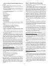
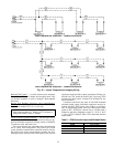
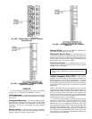
Minimum Damper Position Setting — Setting of the out-
door air damper position is performed in conjunction with a
shortened version of the field run test. This is performed by
first opening DIP (Dual In-line Package) switch no. 4 then
no. 6. See Fig. 18 and 19 and Direct Digital Controls DIP
Switch Configuration section on page 33.
24