


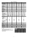
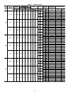
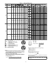
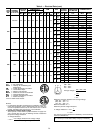
Table 3 — Controls Options and Configurations (Non-Thermostat Applications)
UNIT CONFIGURATION DEFAULT COOLING DEFAULT HEATING
CV or VAV Unit with SPT Sensor
Unoccupied Cooling — 90 F (SPT)
Occupied Cooling — NA
Unoccupied Heating — 55 F (SPT)
Occupied Heating — NA
CV Unit with SPT Sensor and Remote
Start/Stop Switch
Unoccupied Cooling — 90 F (SPT)
Occupied Cooling — 78 F (SPT)
Unoccupied Heating — 55 F (SPT)
Occupied Heating — 68 F (SPT)
VAV Unit Remote Start/Stop Switch Only
Unoccupied Cooling — 90 F (RAT)
Occupied Cooling — 55 F (SAT)
Unoccupied Heating — 55 F (RAT)
Occupied Heating — 68 F (RAT)*
VAV Unit with SPT Sensor and Remote
Start/Stop Switch
Unoccupied Cooling — 90 F (SPT)
Occupied Cooling — 55 F (SAT)
Unoccupied Heating — 55 F (SPT)
Occupied Heating — 68 F (RAT)*
LEGEND
CV — Constant Volume
NA — Not Available
RAT — Return-Air Temperature
SAT — Supply-Air Temperature
SPT — Space Temperature
VAV — Variable Air Volume
*With DIP Switch No. 5 configured to OPEN (Occupied Heat
Enabled).
NOTE: Space temperature sensor and remote start/stop switch are
field-supplied.
• control of modulating economizer damper to provide free
cooling when outdoor conditions are suitable, using
supply-air temperature as a control point
• control of the economizer damper and indoor fan to obtain
unoccupied free cooling
• provide power exhaust output to an external power ex-
haust controller
• support a field test for field checkout
• control of 2 stages of CV power exhaust
• compressor Time Guard (power up, minimum off and on
times)
• compressor lockout during low supply-air temperature
Additional features are provided by accessing the stand-
ard unit control board via software with a computer. These
features are:
• electronic expansion board features (if installed)
• control board diagnostics
• ability to change supply air set point (economizer control)
• ability to change high outdoor temperature lockout set point
(economizer control)
• ability to change power exhaust set points
NOTE: A CV unit without a thermostat requires a field-
supplied sensor for operation.
Features with Sensor Control of Unit (Stand-Alone Appli-
cations — Unit control is limited to CV unoccupied default
set points, 90 F for cooling, 55 F for heating. There are
2 sensor options available:
• T-55 sensor will monitor room temperature and provide
unoccupied override capability (1 hour)
• T-56 sensor will monitor room temperature, provide un-
occupied override capability (1 hour), and provide a tem-
perature offset of 5° F.
Standard features are:
• support of remote occupied/unoccupied input to start and
stop the unit
• cooling capacity control of 3 stages using economizer and
2 compressors to maintain space temperature to an occu-
pied or unoccupied set point
• enable heating or cooling during unoccupied periods as
required to maintain space temperature within the unoc-
cupied set points
• adjustment of space temperature set points of ±5° F when
using a T-56 sensor
Additional features with sensor control of unit (with com-
puter access) are:
• 365 day timeclock with backup (supports minute, hour, day
of week, date, month, and year)
• daylight savings time function
• occupancy control with 8 periods for unit operation
• holiday table containing up to 18 holiday schedules
• ability to initiate timed override from T-55 or T-56 sensors
for a timed period of 1 to 4 hours
• ability to use multiple space temperature sensors to aver-
age the space temperature
• temperature compensated start to calculate early start times
before occupancy
• access to the Display, Maintenance, Configuration,
Service, and Set Point data tables through network
software
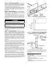
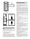
When the unit is equipped with a field-supplied space
temperature sensor and a remote contact closure (remote start/
stop) on the base control board, the occupied default set points
will monitor unit operation. The occupied default set points
are 78 F cooling and 68 F heating. See Fig. 14 for remote
start/stop wiring.
NOTE: For units with a field-supplied space temperature se-
sor which have not had the base unit control board accessed
via software to set an occupancy schedule, the remote start/
stop closure will allow the unit to operate in the pre-
configured occupied default set points (based on return-air
temperature) of 78 F cooling and 68 F heating. Without this
feature, the unit will control to the unoccupied default set
points of 90 F cooling and 55 F heating.
An electronic expansion board may be field-installed to
provide the following features:
• control of modulating economizer damper to maintain in-
door air quality (IAQ) when outdoor conditions are
suitable
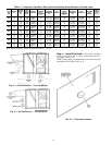
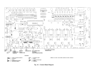
NOTE: The IAQ sensor must be set for current output
(4 to 20 mA), not voltage output. Ensure the jumper on
the sensor is in the upper position. See Fig. 15.
• provide discrete inputs for fan status, filter status, field-
applied status, and demand limit
• provide an output for the external alarm light indicator
• provide power exhaust fire outputs for direct control of
modulated power exhaust stages during fire orsmoke modes
• control of smokecontrol modes including evacuation, smoke
purge, pressurization, and fire shutdown (modulating power
exhaust required)
When the unit is connected to the CCN (Carrier Comfort
Network), the following expansion board features can be
utilized:
• perform Demand Limit functions based on CCN loadshed
commands or the state of the discrete input
• alarm monitoring of all key parameters
• CCN protocol
• provides CCN IAQ participation
See Carrier TEMP or VVT (Variable Volume and Tem-
perature) literature for complete TEMP (single zone) or VVT
(multi-zone) application information.
14