


At the upper right corner of the board is a set of 5 pins and
jumper, which determines the time constant for the control.
The time constant is the delay in response built into the con-
trols. The jumper should be on the middle or bottom two
pins, for the maximum time constant. The delay can be
decreased, if desired, by moving the jumper progressively
upward, always jumpering adjacent pins.
At the lower left corner of the board below the terminal
strip is a resistor marked R27. This must be removed in
order to obtain the 0 to 10 vdc signal output. There will not
be a resistor on a factory-supplied module, but a resistor may
be present on a replacement module and must be removed.
The R353 module has a terminal block with 7 connec-
tions available for wiring. The 2 right-hand terminals are for
the 24 vac and common connections. The next 2 terminals
are for the 0 to 10 vdc signal. Consult the wiring label for
wire identification if replacing the module. The 3 left-hand
terminals are not used for this application.
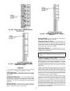
The S353 module has an LED (light-emitting diode), a set
of 4 jumper pins, and 2 potentiometers. The LED will light
whenever the module is activated, providing a visual indi-
cation of the number of exhaust fans running. The jumper
pins are arranged in a square format. Two jumpers are used
to determine the mode of operation (direct or reverse). The
2 jumpers must be arranged horizontally for direct action
(factory set).
At the top of the module are two potentiometers. The left
potentiometer adjusts the offset. The right potentiometer
adjusts the differential. The potentiometers are factory set
for a nominal 0 in. wg building pressure.
The offset set point is defined as the point at which a mod-
ule turns off a fan, and is measured in terms of percent of the
input signal. For control purposes, 0 offset is at an arbitrary
‘‘floor’’ which is established at 10% of the input signal, or
1 vdc. In this example, the first stage will turn off at 30%
(3 vdc), and the offset potentiometer will be set at 20%.
The second stage will turn off at 50% signal (5 vdc), and the
offset potentiometer will be set at 40%. The fourth stage is
at the maximum 75% offset, which equates to 85% signal
or 8.5 vdc. The offset potentiometer is calibrated in 10%
increments.
Table 8 relates building pressure to signal level.
Table 8 — Potentiometer Signal Levels
BUILDING PRESSURE
(in. wg)
SIGNAL LEVEL
(vdc)
−0.50 2
−0.25 4
0.00 6
0.25 8
0.50 10
If the building pressure is controlled at 0 in. wg, offset of
the first stage should be set at 50%, which equates to 60%
of the input signal, or 6 vdc. The other stages can then be set
as desired between 50% and 75%.
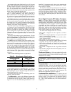
The default offset set points for modulating power ex-
haust are shown in Table 9.
The differential set point is the difference between the
turn off point and the turn on point for each module. It also
is calibrated in terms of percent of input signal, and has a
range of 1% to 7%. The differential potentiometer is cali-
brated in 1% increments, and is factory set at approximately
3%. It is recommended to leave the set point at 3%, to mini-
mize cycling of the fans.
The offset and differential potentiometers have been fac-
tory set for atmospheric pressure. Do not change these
settings until there is some experience with the building. In
most cases the factory settings will be satisfactory. How-
ever, if the building pressure is not being maintained as de-
sired, then some minor adjusting on a trial and error basis
can be made.
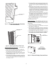
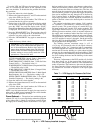
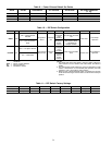
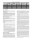
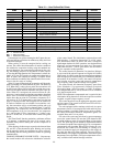
Direct Digital Controls DIP Switch Configura-
tion —
The Direct Digital Control (DDC) board must be
configured for each application. The DDC board is config-
ured through the DIP switches located on the board. There
are 8 DIP switches which configure 8 different applications
of the DDC. See Table 10. DIP switch 1 is on the left of the
block. DIP switch 8 is on the right of the block. To open a
DIP switch, push the switch up with suitable tool (small-
blade screwdriver). To close a DIP switch, push the switch
down. Factory settings are shown in Table 11.
The DIP switch configurations are as follows:
• DIP switch 1 configures the unit to operate as a VAV or
CV unit
• DIP switch 2 configures the unit to use a space sensor (VAV
units) or a thermostat (CV units)
• DIP switch 3 configures the DDC for use with an elec-
tronic expansion board
• DIP switch 4 is used to field test the unit
• DIP switch 5 is used to enable occupied heating (VAV units)
or specify the type of power exhaust (CV units)
• DIP switch 6 configures the Time Guard override and,
when used with the field test function, sets the minimum
damper position
• DIP switch 7 configures the unit for gas heat or electric
heat
• DIP switch 8 configures the unit for heat pump or air con-
ditioner operation.
Crankcase Heater — Units are equipped with crank-
case heaters. Crankcase heaters are energized as long as there
is power supplied to unit. Crankcase heaters deenergize while
compressors are running.
IMPORTANT: To prevent damage to compressors, crank-
case heater should be energized 24-hours prior to
start-up.
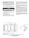
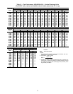
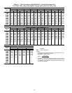
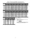
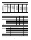
Evaporator Fan — Fan belt and fixed pulleys are factory-
installed. See Tables 12-16 for fan performance and motor
limitations data. Remove tape from fan pulley, and be sure
that fans rotate in the proper direction. See Table 17 for air
quantity limits. Static pressure drop for power exhaust is neg-
ligible. To alter fan performance, see Evaporator Fan
Performance Adjustment section on page 46.
Condenser Fans and Motors — Condenser fans and
motors are factory set. Refer to Condenser-Fan Adjustment
section on page 47 as required. Be sure that fans rotate in
the proper direction. Fan no. 2 (sizes 024-034) and fans
no. 3 and 4 (sizes 038-048) are cycled on the outdoor-air
temperature.
33