


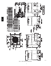
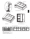
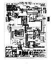
9
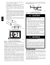
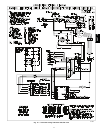
POWER
SUPPLY
FIELD-SUPPLIED
FUSED DISCONNECT
HIGHVOLTAGE
POWER LEADS
(SEE UNITWIRING
LABEL
)
EQUIP GR
CONTROL BOX
LOW-VOLTAGE
POWER LEADS
(SEE UNIT
WIRING LABEL
)
W1
Y
G
R
C
WHT(W1)
YEL(Y)
GRN(G)
RED(R)
BRN(C)
THERMOSTAT
(TYPICAL)
ORN(O)
3-PHASE SHOWN
1-PHASE USES
TWO POWER
LEADS
W2
VIO (W2)
O
SPLICE BOX
DH
BLU(DH)
3-Phase
Only
GRA(Y2)
A09071
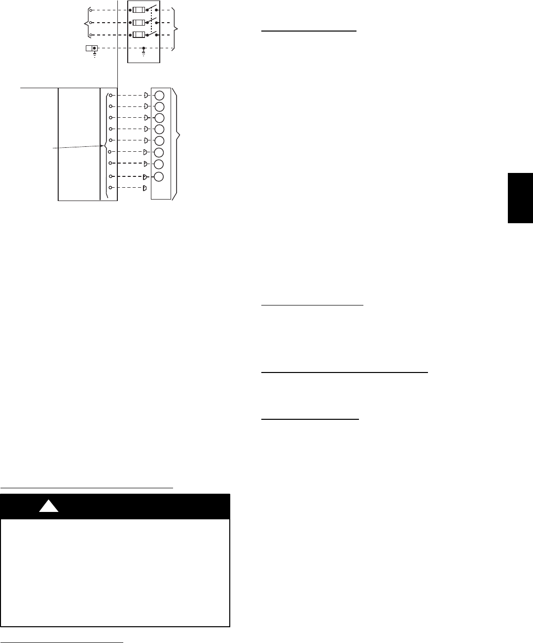
Fig. 10 -- High -- and Control--Voltage Connections
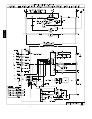
Single phase units:
1. Run the high -- voltage (L1, L2) and ground lead into the
control box.
2. Connect ground lead to chassis ground connection.
3. Locate the black and yellow wires connected to the line side
of the contactor.
4. Connect field L1 to black wire on connection 11 of the
compressor contactor.
5.ConnectfieldwireL2toyellowwireonconnection23of
the compressor contactor.
Three--phase units:
1. Run the high--voltage (L1, L2, L3) and ground lead into the
control box.
2. Connect ground lead to chassis ground connection.
3. Locate the black and yellow wires connected to the line side
of the contactor.
4. Connect field L1 to black wire on connection 11 of the
compressor contactor.
5.ConnectfieldwireL3toyellowwireonconnection13of
the compressor contactor.
6. Connect field wire L2 to blue wire from compressor.
Special Procedures for 208--V Operation
ELECTRICAL SHOCK HAZARD
Failure to follow this warning could result in personal
injury or death.
Before installing or servicing system, always turn off main
power to system. Tag the disconnect switch with a suitable
warning label. With disconnect switch open, move black
wire from transformer (3/16 in.) terminal marked 230 to
terminal marked 208. This retaps transformer to primary
voltage of 208 vac.
!
WARNING
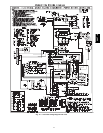
Control Voltage Connections
NOTE: Do not use any type of power--stealing thermostat. Unit
control problems may result.
Use no. 18 American Wire Gage (AWG) color-- coded, insulated
(35°C minimum) wires to make the control voltage connections
between the thermostat a nd the unit. If the thermostat is located
more than 100 ft (30.5 m) from the unit (as measured along the
control voltage wires), use no. 16 AWG color-- coded, insulated
(35° C minimum) wires.
Standard Connections
Locate the eight (nine on 3 --phase) low voltage thermostat leads in
24 volt splice box. See Fig. 10 for connection diagram. Run the
low--voltage leads from the thermostat, through the control wiring
inlet hole grommet (Fig. 2 and 3), and into the low--voltage splice
box. Provide a drip loop before running wires through panel.
Secure and strain r elief all wires so that they do not interfere with
operation of unit. A gray wire is standard on 3--phase units for
connection to an economizer.
If an accessory electric heater is installed, low voltage leads from
heater must be connected to factory s upplied control leads from
Indoor Fan Board P4 connector.
NOTE: If the unit 24V wires do not have a matching receptacle,
cut the 24V wires from the electric heater plug, strip the ends, and
wire nut together to match the schematic connections. If the electric
heater 24V wires do not have a matching plug, cut the 24V wires
from the unit receptacle, strip t he ends, and wire nut together to
match the schematic connections.
Factory w ires are provided for electric heat staging W1 and W2
(W2 and W3 on IFB). If room thermostat has only one stage of
supplemental heat, connect white and violet wires shown in Fig. 10
to second stage heat field wire.
Some electric heaters have four control wires (plus common wire).
Consult unit wiring diagram and electric heater wiring diagram for
additional details.
Transformer Protection
The transformer is of the energy--limiting type. It is set to withstand
a 30--second overload or shorted secondary condition. If an
overload or short is present, correct overload c ondition and check
for blown fuse on Interface Fan Board. Replace fuse as required
with correct size and rating.
Accessory Electric Heaters Installation
Electric heaters may be installed with the 50VT--A units per
instructions supplied with electric heater package. See unit rating
plate for factory--approved electric heater kits.
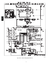
Sequence of Operation
a. CONTINUOUS FAN
(1.) Thermostat closes circuit R to G energizing the
blower motor for continuous fan.
b. COOLING MODE
(1.) If indoor temperature is above temperature set
point, thermostat closes circuits R to G, R to Y and
R to O--The unit delivers cooling airflow.
c. ELECTRIC HEATING MODE
(1.) Thermostat closes circuit R to W/W1, or W2 and R
to G. There are no on or off delays.
d. HEAT PUMP HEAT ING MODE
(1.) Thermostat closes circuits R to G and R to Y. The
compressor, indoor and outdoor fans are energized.
e. HEAT PUMP HEATING WITH AUXILIARY
ELECTRIC HEAT
(1.) Thermostat closes circuits R to G, R to Y and R to
W/W1 or W2. The compressor, indoor and outdoor
fans are energized, as well as the electric heat
relays.
f. DEFROST MODE
The defrost mode is automatically energized by the
defrost board during heating mode. The defrost board
energizes “O” (reversing valve) and “W2” (electric
heat). It also de--energizes the outdoor fan. When defrost
is complete, unit will return to heating mode. If room
thermostat is satisfied during defrost, unit will shut
down and restart in defrost on next call for heat.
50VT--A