


10
Table 1 – Physical Data -- Unit 50VT-- A
50VT-A24 50VT-A30 50VT-A36 50VT-A42 50VT-A48 50VT-A60
Unit Size 2 2.5 3 3.5 4 5
Shipping Weight (lb)
(kg)
354
161
346
157
426
193
472
214
460
209
506
230
Compressor Quantity 1
Type Scroll
Refrigerant R-410A
Refrigerant Quantity (lb)
Quantity (kg)
11.1
5.0
10.3
4.7
9.9
4.5
11.3
5.1
12.5
5.7
15.2
6.9
RefrigerantMetering Device Indoor TXV, Outdoor Dual Accuraters
Orifice OD (in)
(mm)
0.032 (2)
0.81 (2)
0.037 (2)
0.94 (2)
0.038 (2)
0.97 (2)
0.040 (2)
1.02 (2)
0.040 (2)
1.02 (2)
0.049 (2)
1.24 (2)
Outdoor Coil
Rows...Fins/in,
face area (sq. ft.)
2...21
13.6
2...21
13.6
2...21
13.6
2...21
17.5
2...21
17.5
2...21
23.3
Outdoor Fan
Nominal Airflow (cfm)
Diameter (in.)
Diameter (mm)
Motor h p (rpm)
2500
24
610
1/10 (810)
2700
24
610
1/5 (810)
3100
26
660
1/5 (810)
3100
26
660
1/5 (810)
3100
26
660
1/5 (810)
3500
26
660
1/4 (810)
Indoor Coil
Rows...Fins/in,
face area (sq. ft.)
3...17
3.7
3...17
3.7
3...17
4.7
3...17
4.7
3...17
5.6
3...17
5.6
Indoor Blower
Nominal Airflow (cfm)
Size (in.)
Size (mm)
Motor h p (rpm)
800
10 x 10
254 x 254
1/2
1000
10 x 10
254 x 254
1/2
1200
11 x 10
279 x 254
3/4
1400
11 x 10
279 x 254
3/4
1600
11 x 10
279 x 254
1
1750
11 x 10
279 x 254
1
High Pressure Switch (psig)
Cutout
Reset (Auto)
650 +/- 15
420 +/- 25
Loss-of-Charge/Low Pressure Switch (psig)
Cutout
Reset (Auto)
20 +/- 5
45 +/- 10
Return A ir Filters
disposable (in)
(mm)
20x20x1
508x508x25
20x24x1
508x610x25
24x30x1
610x762x25
24x36x1
610x914x25
*Requiredfilter sizes shown are based on the larger of the AHRI(Air ConditioningHeating andRefrigeration Institute) rated cooling airflow or the heating airflow
velocity of 300 ft/minute for throwaway type or 450 ft/minute for high---capacity type. Air filter pressure drop for non---standard fi lters must not exceed 0.08 IN.
W.C.
{ If using accessory filter rack refer to the filter rack installation instructions for correct filter size and quantity.
} For 460 volt units, add 14 lb(6.4 kg) to the weight.
Table 2 – Minimum Airflow for Reliable Electric Heater Operation (CFM)
SIZE 50VT--A24 50VT--A30 50VT--A36 50VT--A42 50VT--A48 50VT--A60
AIRFLOW (CFM) 800 1025 1250 1400 1710 1800
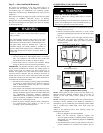
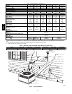
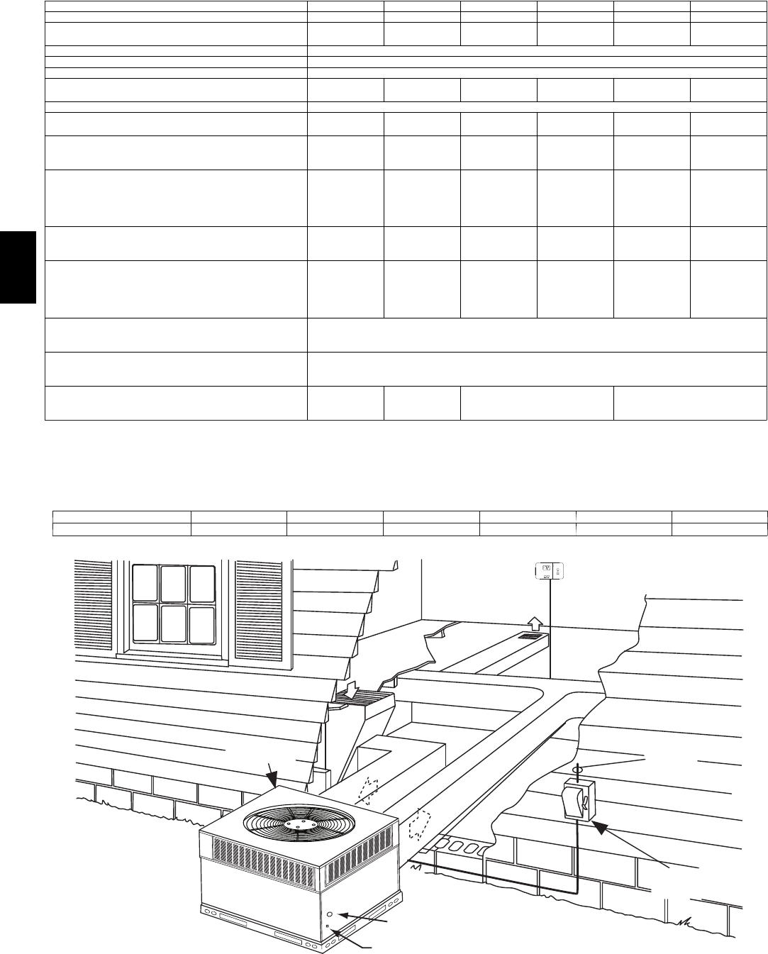
INDOOR
THERMOSTAT
DISCONNECT
PER NEC
FROM
POWER
SOURCE
RETURN
AIR
TOP COVER
POWER ENTRY
CONTROL ENTRY
A09098
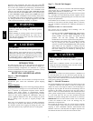
Fig. 11 -- Typical Installation
50VT--A