


2
Recognize safety information. This is the safety--alert symbol
.
When you see this symbol on the unit and in instructions or manu-
als, be alert to the potential for personal injury. Understand these
signal words: DANGER, WARNING, and CAUTION. These
words are used with the safety--alert symbol. DANGER identifies
the most serious hazards which will result in severe personal injury
or death. WARNING signifies hazards which could result in per-
sonal injury or death. CAUTION is used to identify unsafe practic-
es which ma y result in minor personal injury or product and prop-
erty damage. NOTE is used to highlight suggestions which will
result in enhanced installation, reliability , or operation.
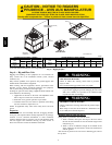
ELECTRICAL SHOCK HAZARD
Failure to follow this warning could result in personal
injury or death.
Before installing or servicing system, always turn off main
power to system and install lockout tag. There may be
more than one disconnect switch. Turn of f accessory heater
power switch if applicable.
!
WARNING
CUT HAZARD
Failure to follow this caution may result in personal injury .
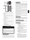
When removing access panels (see Fig. 21) or performing
maintenance functions inside your unit, be aware of sharp
sheet metal parts and screws. Although special care is taken
to reduce sharp edges to a minimum, be extremely careful
when handling parts or reaching into the unit.
!
CAUTION
INTRODUCTION
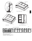
The 50VT -- A heat pump is fully self--contained and designed for
outdoor installation. (See Fig. 1) Standard units are shipped in a
horizontal--discharge configuration for installation on a ground
level slab. Standard units can be converted to downflow (vertical)
discharge configurations for rooftop applications.
RECEIVING AND INSTALLATION
Step 1 — Check Equipment
Identify Unit
The unit model number and serial number are stamped on the unit
identification plate. Check this information against shipping
papers.
Inspect Shipment
Inspect for shipping damage before removing packaging material.
If unit appears to be damaged or is torn loose from its anchorage,
have it examined by transportation inspectors before removal.
Forward claim papers directly to transportation company.
Manufacturer is not responsible for any damage incurred in transit.
Check all items against shipping list. Immediately notify the
nearest equipment distributor if any item is missing. To prevent
loss or damage, leave all parts in original packages until
installation.
If the unit is to be mounted on a curb in a downflow application,
review Step 5 to determine which method is to be used to remove
the downflow panels before rigging and lifting into place. The
panel removal process may require the unit to be on the ground.
Step 2 — Provide Unit Support
Roof Curb
Install accessory roof curb in accordance with instructions shipped
with curb (See Fig. 4). Install insulation, cant strips, roofing, and
flashing. Ductwork must be attached to curb.
IMPORTANT: The gasketing of the unit to the roof curb is critical
for a watertight seal. Install gasketing material supplied with the
roof curb. Improperly applied gasketing also can result in air l eaks
and poor unit performance.
Curb should be level to within 1/4 in. (6 mm) (See Fig. 7). This is
necessary for unit drain to function properly. Refer to accessory
roof curb installation instructions for additional information as
required.
Installation on older “G” series roof curbs.
Two accessory kits are available t o aid in installing a new “G”
series unit on an old “G” roof curb.
1. Accessory kit number CPADCURB001A00, (small chassis)
and accessory kit number CPADCURB002A00, (large
chassis) includes roof curb adapter and gaskets for the
perimeter seal and duct openings. No additional
modifications to the curb are required when using this kit.
2. An alternative to the adapter curb is to modify the existing
curb by removing the outer horizontal flange and use
accessory kit number CPGSKTKIT001A00 which includes
spacer blocks (for easy alignment to existing curb) and
gaskets for the perimeter seal and duct openings. This kit is
used when existing curb is modified by removing outer
horizontal flange.
UNIT/STRUCTURAL DAMAGE HAZARD
Failure to follow this caution may result in property
damage.
Ensure there is sufficient clearance for saw blade when
cutting the outer horizontal flange of the roof curb so there
is no damage to the roof or flashing.
!
CAUTION
Slab Mount
Place the unit on a solid, level concrete pad that is a minimum of 4
in. (102 mm) thick with 2 in. (51 mm) above grade (See Fig. 8).
The slab should extend approximately 2 in. (51 mm) beyond the
casing on all 4 sides of the unit. Do not secure the unit to the slab
except when required by local codes.
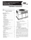
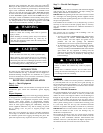
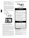
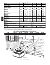
Step 3 — Provide Clearances
The required minimum service clearances are shown in Fig. 2 and
3. Adequate ventilation and outdoor air must be provided. The
outdoor fan draws air through the outdoor coil and discharges it
through the top fan grille. Be sure that the fan discharge does not
recirculate to the outdoor coil. Do not locate the unit in either a
corner or under an overhead obstruction. The minimum clearance
under a partial overhang (such as a normal house overhang) is 48
in. (1219 mm) above the unit top. The maximum horizontal
extension of a partial overhang must not exceed 48 in. (1219 mm).
IMPORTANT: Do not restrict outdoor airflow. An air restriction
at either the outdoor--air inlet or the fan discharge may be
detrimental to compressor life.
Do not place the unit where water, ice, or snow from an overhang
or roof will damage or flood the unit. Do not install the unit on
carpeting or other combustible materials. Slab -- mounted units
should be at least 4 in. (102 mm) above the highest expected water
and runoff levels. Do not use unit if it has been under water.
50VT--A