


5
RETURN
AIR
SMALL
BASE
UNIT
SUPPLY
AIR
LARGE
BASE
UNIT
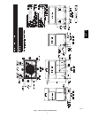
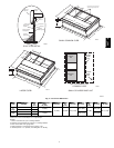
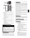
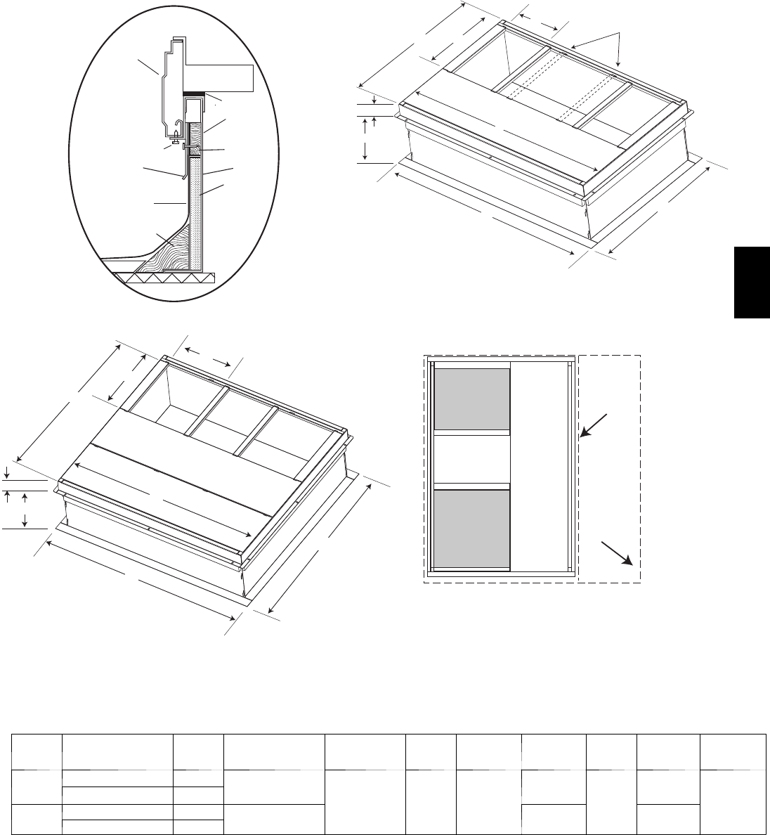
UNIT PLACEMENT ON
COMMON CURB
LARGE CURB
SMALL OR LARGE BASE UNIT
SMALL/COMMON CURB
ROOF CURB DETAIL
Wood nailer*
Roofcurb*
Insulation
(field supplied)
*Provided with roofcurb
Cant strip
field supplied
Roofing material
field supplied
Flashing field
supplied
HVAC unit
base rails
Roofcurb
Sealing
Gasket
HVAC unit
basepan
Anchor screw
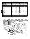
A09090
A09413
A09094
A09415
C
B
A
F
D
E
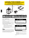
Dashed lines show cross support
location for large basepan units.
G
H
C
B
A
F
D
E
G
H
A09414
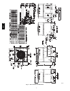
Fig. 4 -- Roof Curb Dimensions
UNIT
SIZE
CATALOG
NUMBER
A
IN.
(mm)
B (small/common
base)
IN. (mm)*
B (large base)
IN. (mm)*
C
IN.
(mm)
D
IN. (mm)
E
IN. (mm)
F
IN.
(mm)
G
IN. (mm)
H
IN. (mm)
Small
or
Large
CPRFCURB010A00 11 (279)
10 (254)
14 (356) 16 (406) 47.8 (1214)
32.4 (822)
2.7 (69)
30.6 (778)
46.1 (1170)
CPRFCURB011A00 14 (356)
Large
CPRFCURB012A00 11 (279)
14 (356) 43.9 (1116) 42.2 (1072)
CPRFCURB013A00 14 (356)
* Part Numbers CPRCURB010A00 and CPRCURB011A00 can be used on both small and large basepan units. The cross supports must be located based on
whether the unit isa small basepan or a large basepan.
NOTES:
1.Roof curb must be set up for unit being installed.
2. Seal strip must be applied, as required, to unit b eing installed.
3. Roof curb is made of16---gauge steel.
4. Attach ductwork to curb (flanges of duct rest o n curb).
5. Insulated panels: 1---in. (25 mm) thick fiberglass 1 lb. density .
50VT--A