


18
turning backwards, the dif ference between compressor suction a nd
discharge pressures may be near zero.
Checking and Adjusting Refrigerant Charge
The refrigerant system is fully charged with Puron (R--410A)
refrigerant and is tested and factory sealed.
NOTE: Adjustment of the refrigerant charge is not required
unless the unit is suspected of not having the proper Puron
(R--410A) charge.
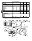
A subcooling charging chart is attached to the inside of the
compressor access panel (see Fig. 21). The chart includes the
required liquid line temperature at given discharge line pressures
and outdoor ambient temperatures.
An accurate thermocouple-- or thermistor--type thermometer, and a
gauge manifold are required when using the subcooling charging
method for evaluating the unit charge. Do not use mercury or small
dial--type thermometers because they are not adequate for this type
of measurement.
NOTE: Allow system to operate for a minimum of 15 minutes
before checking or adjusting refrigerant charge.
IMPORTANT: When evaluating the refrigerant charge, an
indicated adjustment to the specified factory char ge must always be
very minimal. If a substantial adjustment is indicated, an abnormal
condition exists somewhere in the cooling system, such as
insuf ficient airflow across either coil or both coils.
Proceed as follows:
1. Remove caps from low-- and high--pressure service fittings.
2. Using hoses with valve c ore depressors, attach low-- and
high--pressure gauge hoses to low-- and high-- pressure
service fittings, respectively.
3. Start unit and let run until system pressures stabilize.
4. Measure and record the following:
a. Outdoor ambient-- air temperature (°F[°C] db).
b. Liquid line temperature (°F[°C]) at TXV.
c. Discharge (high -- side) pressure (psig).
d. Suction (low--side) pressure (psig) (for reference only).
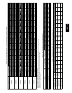
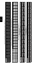
5. Using Cooling Charging Charts compare outdoor--air
temperature (°F[°C] db) with the discharge line pressure
(psig) to determine desired system operating liquid line
temperature (See Fig. 18).
6. Compare actual liquid line temperature with desired liquid
line temperature. Using a tolerance of ±2°F(±1.1°C), add
refrigerant if actual temperature is m ore than 2°F(1.1°C)
higher than proper liquid line temperature, or remove
refrigerant if actual temperature is m ore than 2°F(1.1°C)
lower than required liquid line temperature.
NOTE: If the problem causing the inaccurate readings is a
refrigerant leak, refer to Check for Refrigerant Leaks section.
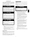
Indoor Airflow and Airflow Adjustments
UNIT OPERATION HAZARD
Failure to follow this caution may result in unit damage.
For cooling operation, the recommended airflow is 350 to
450 cfm for each 12,000 Btuh of rated cooling capacity. For
heating operation, the airflow must produce a temperature
rise that falls within the range stamped on the unit rating
plate.
CAUTION
!
NOTE: Be sure that all supply--and return--air grilles are open,
free from obstructions, and adjusted properly.
ELECTRICAL SHOCK HAZARD
Failure to follow this warning could result in personal
injury or death.
Disconnect electrical power to the unit and install lockout
tag before changing blower speed.
!
WARNING
This unit is factory-set up for use with a single cooling fan speed.
In addition, this unit has the field-selectable capability to run t wo
different cooling fan speeds: The rated cooling fan speed (350~400
CFM/Ton) and an enhanced dehumidification fan speed (As low as
320 CFM/Ton) for use with either a dehumidistat or a thermostat
that supports dehumidification.
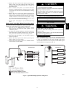
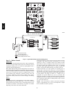
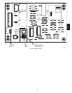
The cooling speed is marked “LOW” on the interface fan board
(IFB) (See Fig. 16) . The factory-shipped settings are noted in
Table 4. There are 4 additional speed tap wires available for use in
either electric heating or cooling (For color coding on the indoor
fan motor leads, see Table 3). The additional 4 speed tap wires are
shipped loose with vinyl caps and are located in the control box,
near the interface fan board (IFB) (See Fig. 16).
Single Cooling Fan Speed Set-up (Dehumidification
feature not
used)
To change cooling speed:
1. Remove the vinyl cap off of the desired speed tap wire
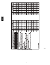
(Refer to Table 3 for color coding). Add the wet coil
pressure drop in T a ble 7 to the system static to determine the
correct cooling airflow speed in Table 4 that will deliver the
nominal cooling airflow as listed in Table 1 for each size.
2. Remove the current speed tap wire from the “LOW”
terminal on the i nterface fan board (IFB) (See Fig. 16) and
place vinyl cap over the connector on the wire.
3. Connect the desired speed tap wire to the “LOW” terminal
on the interface fan board (IFB).
NOTE: If accessory electric heat is installed, and the electric heat
fan speed is chosen to be the same as the normal cooling fan speed,
the dry airflow must meet or exceed the minimum airflow speed
specified in Table 2 for the specific size unit.
Two Cooling Fan Speeds Set-up (Dehumidification
feature
used)
IMPORTANT: Dehumidification control must open control
circuit on humidity rise above set point.
Use of the dehumidification cooling fan speed requires use of
either a 24 VAC dehumidistat or a thermostat which includes
control of a 24 VAC dehumidistat connection. In either case, the
dehumidification control must open the control circuit on humidity
rise above the dehumidification set point.
1. Using Fig. 16, move the two pin DEHUM jumper from the
“STD” position to the “DEHUM” position.
2. Remove fan speed tap wire from the “LOW” terminal on
the interface fan board (IFB) (See Fig. 16).
3. Determine correct normal cooling fan speed for unit and
application. Add the wet coil pressure drop in Table 7 to
the system static to determine the correct cooling airflow
speed in Table 4 that will deliver the nominal cooling
airflow as listed in Table 1 for each size.
NOTE: If accessory electric heat is installed, the dry
airflow must m eet or exceed the minimum airflow speed
specified in Table 2 for the specific size unit. The electric
heat fan speed will be the same as the normal cooling fan
speed.
50VT--A