


28
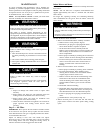
Puron (R--410A) Refrigerant Charging
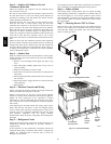
Refer to unit information plate and charging chart. Some R--410A
refrigerant cylinders contain a dip tube to allow liquid refrigerant to
flow from cylinder in upright position. For cylinders equipped
with a dip tube, charge Puron units with cylinder in upright
position and a commercial metering device in manifold hose.
Char ge refrigerant into suction--line.
Step 13 — System Information
Loss of Charge Switch
The loss of charge switch is a protective device wired into control
circuit (low voltage). It shuts off the compressor if abnormally low
pressures are present in the refrigeration circuit.
NOTE: B ecause these switches are attached to refrigeration
system under pressure, it is not advisable to remove this device for
troubleshooting unless you are reasonably certain that a problem
exists. If switch must be removed, remove and recover all system
charge so that pressure gauges read 0 psig. Never open system
without breaking vacuum with dry nitrogen.
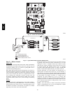
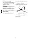
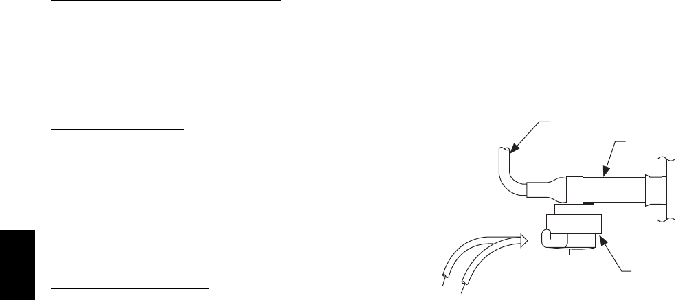
Check Defrost Thermostat
The defrost thermostat is usually located on the lowest liquid
leaving circuit of the left condenser coil (see Fig. 22). The
thermostat closes at 32_F(0_C) and opens at 65_F(18_C).
The defrost thermostat signals heat pump that conditions are right
for defrost or that conditions have changed to terminate defrost. It
is a thermally actuated switch clamped to outdoor coil to sense its
temperature. Normal temperature range is closed at 32_ 3_F(0
1.7_C) and open at 65_ 5_F(18 2.8_C).
NOTE: The defrost thermostat must be located on the liquid side
of the outdoor coil on the bottom circuit and as close to the coil as
possible.
FEEDER TUBE
STUB TUBE
DEFROST
THERMOSTAT
C99029
Fig. 22 -- Defrost Thermostat
TROUBLESHOOTING
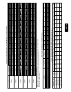
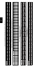
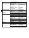
Refer to the Cooling and Heating Troubleshooting Chart (Table
10) for troubleshooting information.
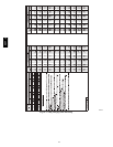
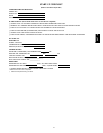
START--UP CHECKLIST
Use the Start--Up Checklist.
50VT--A