


8
screwed or bolted to duct flanges. Use suitable gaskets to
ensure weather--tight and airtight seal.
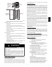
4. All units must have field--supplied filters or accessory filter
rack installed in the return--air side of the unit.
Recommended sizes for filters are shown in Table 1.
5. Size all ductwork for maximum required airflow (either
heating or cooling) for unit being installed. Avoid abrupt
duct size increases or decreases or performance may be
affected.
6. Adequately insulate and weatherproof all ductwork located
outdoors. Insulate ducts passing through unconditioned
space, and use vapor barrier in accordance with latest issue
of Sheet Metal and Air Conditioning Contractors National
Association (SMACNA) and Air Conditioning Contractors
of America (ACCA) minimum installation standards for
heating and air conditioning systems. Secure all ducts to
building structure.
7. Flash, weatherproof, and vibration-- isolate all openings in
building structure in accordance with local codes and good
building practices.
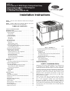
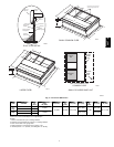
A
B
C
MAXIMUM ALLOWABLE
DIFFERENCE in. (mm)
A-C
1/4
1/4
1/4
(6.35)
(6.35)
(6.35)
A-B
B-C
A07925
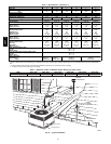
Fig. 7 -- Unit Leveling Tolerances
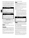
OPTIONAL
RETURN
AIR
OPENING
OPTIONAL
SUPPLY
AIR
OPENING
EVAP. COIL COND. COIL
2˝
(50.8mm)
A07926
Fig. 8 -- Slab Mounting Detail
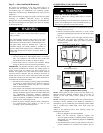
Step 6 — Provide for Condensate Disposal
NOTE: Ensure that condensate--water disposal methods comply
with local codes, restrictions, and practices.
The 50VT-- A units dispose of condensate through a 3/4 in. NPT
female fitting that exits on the compressor end of the unit.
Condensate water can be drained directly onto the roof in rooftop
installations (w here permitted) or onto a gravel apron in ground
level installations. Install a field-- supplied condensate trap at end of
condensate connection to ensure proper drainage. Make sure that
the outlet of the trap is at least 1 in. (25 mm) lower than the
drain--pan condensate connection to prevent the pan from
overflowing. Prime the trap with water. When using a gravel apron,
make sure it slopes away from the unit.
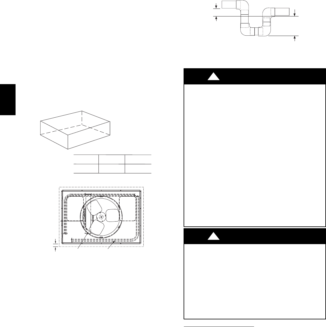
If the installation requires draining the condensate water away from
the unit, install a field--supplied 2 --in. (51mm) trap at the
condensate connection to ensure proper drainage. Condensate trap
is available as an accessory or is field--supplied. Make sure that the
outlet of the trap is at least 1 in. (25 mm) lower than the unit
drain--pan condensate connection to prevent the pan from
overflowing. Connect a drain tube using a minimum of
field -- supplied 3/4--in. PVC or field-- supplied 3/4 -- in. copper pipe
at outlet end of the 2--in. (51 mm) trap. (See Fig. 9) Do not
undersize the tube. Pitch the drain tube downward at a slope of at
least 1 in. (25 mm) every 10 ft (3 m) of horizontal run. Be sure to
check the drain trough for leaks. Prime the trap at the beginning of
the cooling season start--up.
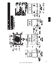
TRAP
OUTLET
1-in. (25 mm) min.
2-in. (51 mm) min.
A09052
Fig. 9 -- Condensate Trap
Step 7 — Install Electrical Connections
UNIT COMPONENT DAMAGE HAZARD
Failureto follow t his caution may result in damage to theunit
being installed.
1. Ma ke all electrical connections in accordance with NEC
NFPA 70 (latest edition) and local electrical codes
governing such wiring. In Canada, all electrical
connections must be in accordance with CSA s tandard
C22.1 Canadian Electrical Code Part 1 and applicable
local codes. Refer to unit wiring diagram.
2. Use only copper conductor for connections between
field -- supplied electrical disconnect switch and unit. DO
NOT USE ALUMINUM WIRE.
3. Be sure that high-- voltage power to unit is within
operating voltage range indicated on unit rating plate. On
3--phase units, ensure phases are balanced within 2
percent. Consult local power company for correction of
improper voltage and/or phase imbalance.
4. Do not damage internal components when drilling
through any panel to mount electrical hardware, conduit,
etc.
!
CAUTION
ELECTRICAL SHOCK HAZARD
Failure to follow this warning could result in personalinjury
or death.
The unit cabinet must have an uninterrupted, unbroken
electrical ground. This ground may consist of an electrical
wire connected to the unit ground screw in the control
compartment,orconduitapprovedforelectricalgroundwhen
installed in accordance with NEC,NFPA 70 National Fire
Protection Association (latest edition) (in Canada, Canadian
Electrical Code CSA C22.1) and local electrical codes.
!
WARNING
High--Voltage Connections
The unit must have a separate electrical service with a
field -- supplied, waterproof disconnect switch mounted at, or within
sight from the unit. Refer to the unit rating plate, NEC and local
codes for maximum fuse/circuit breaker size and minimum circuit
amps (ampacity) for wire sizing.
The field--supplied disconnect may be mounted on the unit over
the high--voltage inlet hole when the standard power and
low--voltage entry points are used. See Fig. 2 and 3 for acceptable
location. Remove high voltage knockout.
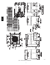
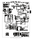
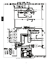
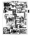
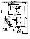
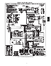
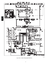
See unit wiring label (Fig. 12--14) and Fig. 10 for reference when
making high voltage connections. Proceed as follows to complete
the high--voltage connections to the unit.
50VT--A