


19
4. Remove the vinyl cap off of the desired speed tap wire
(Refer to Table 3 for color coding) for the normal cooling
fan speed and place desired speed tap wire on “HIGH” on
the interface board.
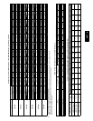
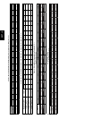
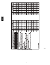
5. Refer to airflow tables (Table 4) to determine allowable
speeds for the dehumidification cooling fan speed. In Table
4, speeds that are not allowed for dehumidification cooling
are shaded.
6. Remove the vinyl cap off of the desired speed tap wire
(Refer to Table 3 for color coding) for the dehumidification
cooling fan speed and place desired speed tap wire on the
“LOW” connection on the interface board (IFB). Verify
that static pressure is in the acceptable range for the speed
tap to be used for dehumidification cooling.
7. Use any spare vinyl plugs to cap any unused speed tap
wires.
Single Speed Cooling With Higher Electric Heat Speed
This unit can also be configured to operate with single speed
cooling and a higher speed for an accessory electric heater .
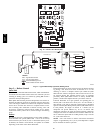
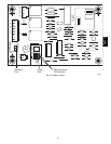
1. Move the two pin DEHUM jumper located on control
board (see Fig. 16) from the “STD” position to the
“DEHUM” position.
2. See Table 2 for minimum airflow for electric heat operation.
Add electric heater and filter pressure drop to duct system
static pressure to determine total external static pressure.
3. Select speed tap from Table 4 that will achieve required
airflow from Table 2.
4. Remove the vinyl cap off of the desired speed tap wire
(Refer to Table 3 for color coding).
5. Connect the desired speed tap wire to t he “HIGH” terminal
on the interface fan board (IFB).
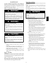
UNIT OPERATION HAZARD
Failure to follow this caution may result in unit component
damage or improper operation.
To use this mode, a speed connection must be made on the
“HIGH” terminal that meets or exceeds the minimum
airflow found in Table 2.
!
CAUTION
Table 3 – Color Coding for Indoor Fan Motor Leads
Black = High Speed
Orange = Med--High Speed
Red = Med Speed
Pink = Med--Low Speed
Blue = Low Speed
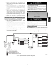
ELECTRICAL SHOCK HAZARD
Failure to follow this warning could result in personal
injury or death.
Disconnect electrical power to the unit and install lockout
tag before changing blower speed.
!
WARNING
Continuous Fan Operation
When the DEHUM feature is not used, the continuous fan speed
will be the same as cooling fan speed. When the DEHUM feature
is used, the continuous fan will operate on IFB “LOW” speed
when the DH c ontrol lead is not energized, or IFB “HIGH” speed
when the DH lead is ener gized (see Fig. 16).
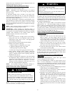
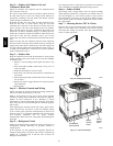
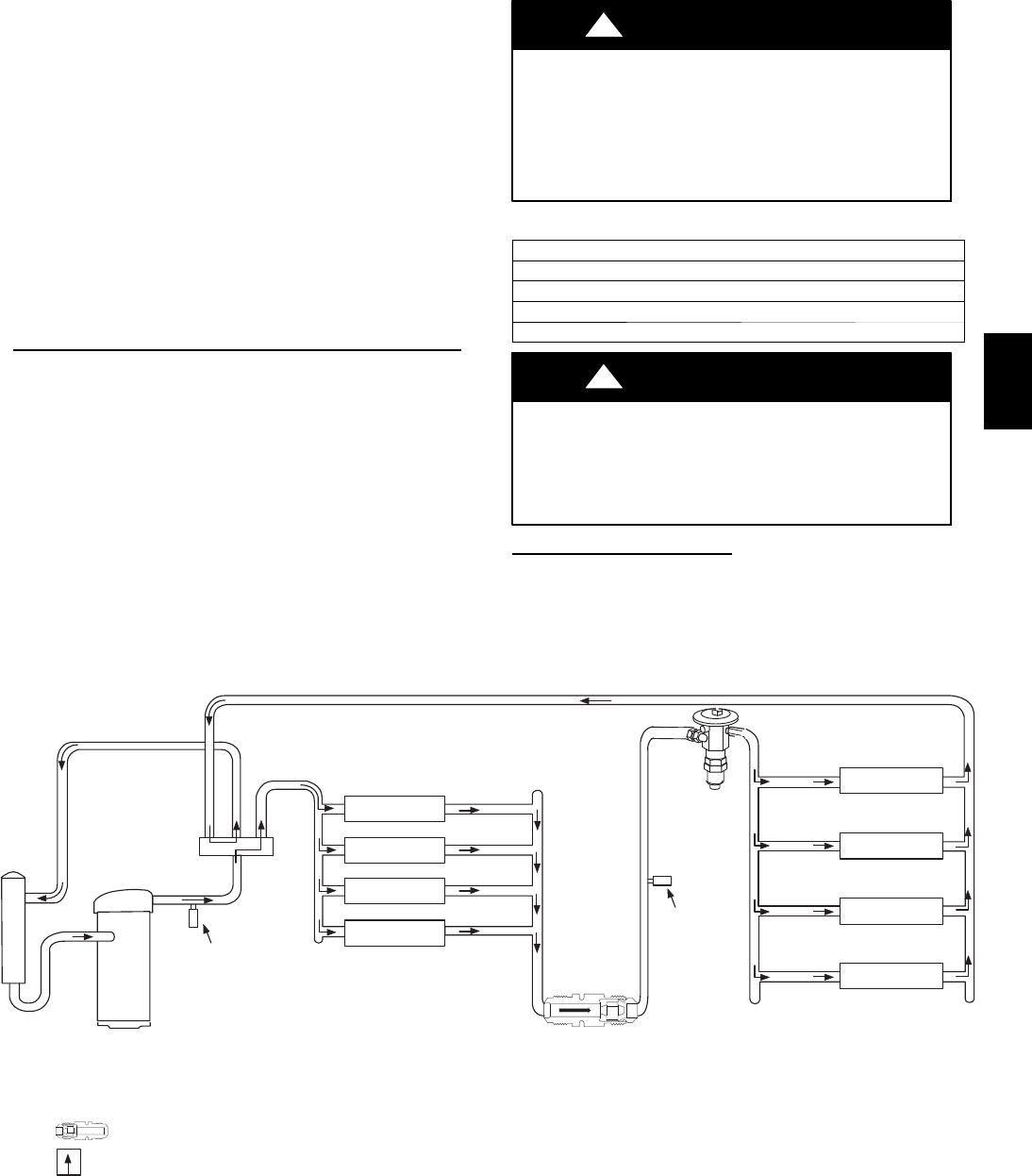
COMPRESSOR
ACCUMULATOR
OUTDOOR COIL
INDOOR COIL
LCS
LEGEND
HPS – High Pressure Switch
LCS – Loss of Charge Switch
Accurater
®
Metering De vice
Arrow indicates direction of flo w
TXV in Metering
Position
Bypass
Position
HP S
C03011
Fig. 15 -- Typical Heat Pump Operation, Cooling Mode
50VT--A