


17
PRE--START--UP
FIRE, EXPLOSION, ELECTRICAL SHOCK AND
ENVIRONMENTAL HAZARD
Failure to follow thiswarning could result in personal injury,
death or property damage.
1. Follow recognized safety practices and wear protective
goggles when checking or servicing refrigerant system.
2. Relieve and recover all refrigerant from system before
touching or disturbing compressor plug if refrigerant
leak is suspected around compressor terminals.
3. Do not remove compressor plug until all electrical
sources are disconnected and tagged.
4. Never attempt to repair soldered connection while
refrigerant system is under pressure.
5. Do not use torch to remove any component. System
contains oil and refrigerant under pressure.
To remove a component, wear protective goggles and
proceed as follows:
a. Shut off electrical power to unitand install lockout
tag.
b. Relieve and reclaim all refrigerant from system
using both high-- and low -- pressure ports.
c. Cut component connecting tubing with tubing
cutter and remove component from unit.
d. Carefully unsweat remaining tubing stubs when
necessary. Oil can ignite when exposed to torch
flame.
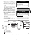
!
WARNING
Use the Start-- Up Checklist supplied at the end of this book and
proceed as follows to inspect and prepare the unit for initial
start--up:
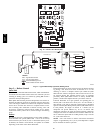
1. Remove all access panels (see Fig. 21).
2. Read and follow instructions on all DANGER, WARNING,
CAUTION, and INFORMATION labels attached to, o r
shipped with, unit.
3. Make the following inspections:
a. Inspect for shipping and handling damages such as
broken lines, loose parts, disconnected wires, etc.
b. Inspect for oil at all refrigerant tubing connections and
on unit base. Detecting oil generally indicates a
refrigerant leak. Leak -- test all refrigerant tubing
connections using electronic leak detector, or
liquid-- soap solution. If a refrigerant leak is detected, see
following Check for Refrigerant Leaks section.
c. Inspect all field and factory--wiring connections. Be sure
that connections are completed and tight. Ensure wires
do not touch refrigerant tubing or sharp sheet metal
edges.
d. Inspect coil fins. If damaged during shipping and
handling, carefully straighten fins with a fin comb.
4. Verify the following conditions:
a. Make sure that outdoor--fan blade is correctly positioned
in fan orifice.
b. M ake sure that air filter(s) is in place.
c. Make sure that condensate drain pan and trap are filled
with water to ensure proper drainage.
d. Make sure that all tools and miscellaneous loose parts
have been removed.
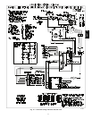
5. Each unit system has 2 Schrader--type ports, one low--side
Schrader fitting located on the suction line, and one
high--side Schrader fitting located on the c ompressor
discharge line. Be sure that caps on the ports are tight.
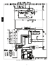
START--UP
Checking Cooling and Heating Control Operation
Start and check the unit for proper control operation as follows:
(1.) Place room thermostat SYSTEM switch or MODE
control in OFF position. Observe that blower
motor starts when FAN mode is placed in FAN ON
position and shuts down when FAN MODE switch
is placed in AUTO position.
(2.) Thermostat:
When the room temperature rises to a point that is
slightly above the cooling control setting of the
thermostat, the thermostat completes the circuit
between thermostat terminal R to terminals Y, O
and G.These completed circuits through the
thermostat connect contactor coil (C) (through unit
wire Y) and Indoor Fan board (through unit wire
G) across the 24 -- v. secondary of transformer
(TRAN).
(3.) Place system switch or MODE control in HEAT
position. Set control above room temperature.
Observe that compressor, outdoor fan, and indoor
blower motors start. Observe that heating cycle
shuts down when control setting is satisfied.
(4.) When using an automatic changeover room
thermostat place both SYSTEM or MODE control
and FAN mode switches in AUTO positions.
Observe that unit operates in Cooling mode when
temperature control is set to “call for Cooling”
(below room temperature), and unit operates in
Heating mode when temperature control is set to
“call for Heating” (above room temperature).
NOTE: Once the compressor has started and then has stopped, it
should not be started again until 5 minutes have elapsed. The
defrost board has a built-- in 5 minute delay between cycles. The 5
minute compressor delay also applies to heat pump heating mode.
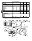
Step 1 — Check for Refrigerant Leaks
Proceed as follows to locate and repair a refrigerant leak and to
charge the unit:
1. Locate leak and make sure that refrigerant system pressure
has been relieved and reclaimed from both high-- and
low--pressure ports.
2. Repair leak following Refrigerant Service procedures.
NOTE: Install a bi--flow filter drier whenever the system has been
opened for repair.
3. Add a small charge of R--410A refrigerant vapor to system
and leak--test unit.
4. Recover refrigerant from refrigerant system and evacuate to
500 microns if no additional leaks are not found.
5. Charge unit with Puron (R-- 410A) refrigerant, using an
electronic scale. Refer to unit rating plate for required
charge.
Step 2 — Start--Up Adjustments
Complete the required procedures given in the Pre--Start--Up
section before starting the unit. Do not jumper any safety devices
when operating the unit. Do not operate the unit in Cooling mode
when the outdoor temperature is below 40_F(4_C) (unless
accessory low--ambient kit is installed).
IMPORTANT: Three--phase, scroll compressors are direction
oriented. Unit must be checked to ensure proper compressor
3--phase power lead orientation. If not corrected within 5 minutes,
the internal protector will shut off the compressor. The 3--phase
power leads to the unit must be reversed to correct rotation. When
50VT--A