


8
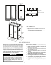
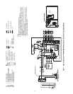
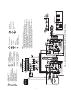
Solenoid Coil
Thermistor
Ground
Indicator Light
G=Green, R=Red
(Comp On) (Alarm Light)
Circuit Breaker
High Pressure Switch
Low Pressure Switch
Fuse
F
a50-8621
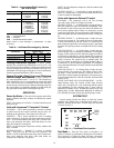
Fig. 4 — Typical Aquazone™ 50PSW036-060 Complete C Control Wiring, Single-Phase
RVS — Reversing Valve Solenoid
TRANS — Transformer
Factory Line Voltage Wiring
Factory Low Voltage Wiring
Field Line Voltage Wiring
Field Low Voltage Wiring
Printed Circuit Trace
Relay/Contactor Coil
Complete C
Complete C
NOTES:
1. Compressor motor thermally protected internally.
2. All wiring to the unit must comply with NEC and local codes.
3. Transformer is wired to 265 v lead (BRN) for 265-1-50 units. For 220/240 v
operation, disconnect BRN lead at L1 and connect ORG lead to L1. Insulate
open ends of BRN and RED leads. Transformer is energy limiting or may have
circuit breaker.
4. FP1 thermistor provides freeze protection for source water. When using anti-
freeze solutions, cut JW3 jumper.
5. Refer to or Thermostat Installation, Application and Operation Manual for con-
trol wiring to the unit. Low voltage wiring must be “Class 1” and voltage rating
equal to or greater than unit supply voltage.
AL — Alarm Relay Contacts
CC — Compressor Contactor
FP1 — Sensor, Source Low Temp Protection
FP2 — Sensor, Load Low Temp Protection
HP — High Pressure Switch
JW1 — Jumper Wire for Alarm
LED — Light-Emitting Diode
LOC — Loss of Charge Pressure Switch
NEC — National Electrical Code
P1 — Field Wiring Terminal Block