


14
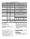
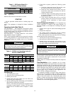
Table 5 — DIP Switch Block S2 —
Accessory 2 Relay Options
LEGEND
NOTE: All other DIP switch combinations are invalid.
START-UP
Use the procedure outlined below to initiate proper unit
start-up.
NOTE: This equipment is designed for indoor installation
only.
Operating Limits (See Table 6)
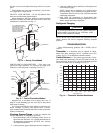
ENVIRONMENT — This equipment is designed for indoor
installation ONLY. Extreme variations in temperature, humidi-
ty and corrosive water or air will adversely affect the unit per-
formance, reliability and service life.
POWER SUPPLY — A voltage variation of ± 10% of name-
plate utilization voltage is acceptable.
NOTE: These operating conditions are not normal or continu-
ous operating conditions. It is assumed that start-up is for the
purpose of bringing the building space up to occupancy
temperature.
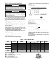
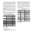
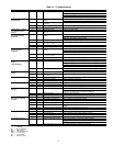
Table 6 — 50PSW Unit Operating Limits (C)
BUILDING COMMISSIONING
BUILDING OPERATING
Unit Start-Up
1. Turn off all power to unit.
2. Adjust all valves to full open position.
3. Restore power to unit.
4. Operate each unit in the cooling cycle. See Table 6 for
unit entering water temperatures.
5. Operate each heat pump in the heating cycle immediately
after checking cooling cycle operation.
NOTE: A time delay will prevent the compressor from
re-starting for approximately 5 minutes. The time delay
function can be overridden on the Complete C control
board.
6. If unit fails to operate, perform the following system
checks:
a. Check the voltage and current. Be sure they com-
ply with electrical data on unit nameplate.
b. Check for loose terminal screws where wire con-
nections have been made on both the line and low-
voltage terminal boards.
c. Check the supply and return piping. Be sure they
are properly connected to the inlet and outlet con-
nections on the unit.
d. If the checks described above fail to reveal the
problem and the unit still will not operate, contact
a trained service technician to ensure proper
diagnosis.
Scroll Compressor Rotation — It is important to be
certain compressor is rotating in the proper direction. To
determine whether or not compressor is rotating in the proper
direction:
1. Connect service gages to suction and discharge pressure
fittings.
2. Energize the compressor.
3. The suction pressure should drop and the discharge
pressure should rise, as is normal on any start-up.
If the suction pressure does not drop and the discharge
pressure does not rise to normal levels:
1. Turn off power to the unit. Install disconnect tag.
2. Reverse any two of the unit power leads.
3. Reapply power to the unit and verify pressures are cor-
rect. The suction and discharge pressure levels should
now move to their normal start-up levels.
After a few minutes of reverse operation, the scroll com-
pressor internal overload protection will open, thus activating
the unit lockout. This requires a manual reset. To reset, turn the
thermostat on and then off.
NOTE: There is a 5-minute time delay before the compressor
will start.
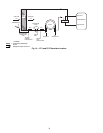
Flow Regulation — Flow regulation can be accom-
plished by two methods. Most water control valves have a flow
adjustment built into the valve. By measuring the pressure drop
through the unit heat exchanger, the flow rate can be deter-
mined. Adjust the water control valve until the flow of 0.09 to
0.13 L/s is achieved. Since the pressure constantly varies, two
pressure gages may be needed in some applications. See
Table 7 for heat exchanger pressure drops.
An alternative method is to install a flow control device.
These devices are typically an orifice of plastic material de-
signed to allow a specified flow rate that are mounted on the
outlet of the water control valve. Occasionally these valves
produce a velocity noise that can be reduced by applying some
back pressure. To accomplish this, slightly close the leaving
isolation valve of the water regulating device.
ACCESSORY 2
RELAY OPTIONS
DIP SWITCH POSITION
456
Digital NSB Off On On
Water Valve — Slow Opening On Off On
NSB — Night Setback
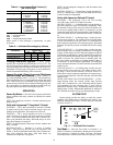
WARNING
When the disconnect switch is closed, high voltage is pres-
ent in some areas of the electrical panel. Exercise caution
when working with the energized equipment.
50PSW
UNIT SIZE
COOLING HEATING
Source
Min/Max
Load
Min/Max
Ambient
Min/Max
Source
Min/Max
Load
Min/Max
Ambient
Min/Max
036 10/43 16/27 7/43 –1/27 16/49 4/29
060,120 10/49 16/32 7/43 –1/27 16/49 4/29
180,360 10/32 16/32 7/43 10/21 27/49 4/29
50PSW
UNIT SIZE
COOLING HEATING
Source
Min/Max
Load
Min/Max
Ambient
Min/Max
Source
Min/Max
Load
Min/Max
Ambient
Min/Max
036 10/49 10/32 7/43 –7/27 16/54 4/29
060,120 10/49 10/32 7/43 –7/27 16/54 4/29
180,360 10/43 10/32 7/43 –7/21 16/49 4/29
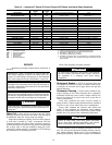
CAUTION
When the compressor is rotating in the wrong direction, the
unit makes an elevated level of noise and does not provide
cooling. Damage to compressor will occur if allowed to
operate in this manner.