


7
Step 6 — Wire Electrical Connections
All field-installed wiring, including the electrical ground,
MUST comply with the National Electrical Code (NEC) as
well as applicable local codes. In addition, all field wiring must
conform to the Class II temperature limitations described in the
NEC.
Operating voltage must be the same voltage and phase as
shown in Table 3.
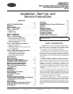
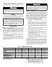
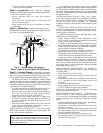
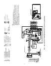
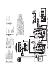
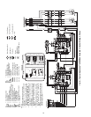
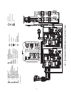
Refer to unit wiring diagrams Fig. 4-8 for a schematic of the
field connections which must be made by the installing (or
electrical) contractor.
Consult the unit wiring diagram located on the inside of the
compressor access panel to ensure proper electrical hookup.
The installing (or electrical) contractor must make the field
connections when using field-supplied disconnect.
Make all final electrical connections with a length of flexi-
ble conduit to minimize vibration and sound transmission to
the building.
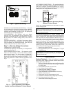
POWER CONNECTION — Line voltage connection is
made by connecting incoming line voltage wires to L1, L2, and
L3 on the power distribution block.
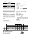
SUPPLY VOLTAGE — Operating voltage to unit must be
within voltage range indicated on unit nameplate.
Voltages between phases must be balanced within 2%.
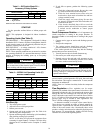
Use the following formula to determine the percentage voltage
imbalance:
% Voltage Imbalance
Example: Supply voltage is 380-3-50.
AB = 372 volts
BC = 376 volts
AC = 384 volts
Determine maximum deviation from average voltage:
(AB) 372 – 377 = 5 v
(BC) 376 – 377 = 1 v
(AC) 384 – 377 = 7 v
Maximum deviation is 7 v.
Determine percent voltage imbalance.
This amount of phase imbalance is satisfactory as it is
below the maximum allowable 2%.
Operation on improper line voltage or excessive phase
imbalance constitutes abuse and may cause damage to electri-
cal components.
NOTE: If more than 2% voltage imbalance is present, contact
local electric utility.
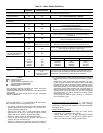
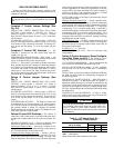
Table 3 — 50PSW Electrical Data
LEGEND
*Time-delay fuse or HACR circuit breaker.
WARNING
To avoid possible injury or death due to electrical shock,
open the power supply disconnect switch and secure it in
an open position during installation. Install lockout tag.
CAUTION
Use only copper conductors for field-installed electrical
wiring. Unit terminals are not designed to accept other
types of conductors. Failure to heed this warning could
result in equipment damage.
= 100 x
max voltage deviation from average voltage
average voltage
Average Voltage =
372 + 376 + 384
3
=
1132
3
= 377
% Voltage Imbalance = 100 x
7
377
= 1.86%
50PSW UNIT
SIZE
VOLTAGE
(V-Ph-Hz)
VOLTAGE RANGE
MIN/MAX
COMPRESSOR
TOTAL
FLA
MCA MOCP*
RLA LRA QTY
036
220/240-1-50 198/264 13.5 67 1 13.5 16.9 30
380/420-3-50 342/462 5.4 38 1 5.4 6.8 15
060
220/240-1-50 198/264 24.5 153 1 24.5 30.6 50
380/420-3-50 342/462 9.6 74 1 9.6 12.0 20
120
220/240-1-50 198/264 24.5 153 2 49.0 55.1 80
380/420-3-50 342/462 9.6 74 2 19.2 21.6 30
180
220/240-1-50 198/264 44.9 273 1 44.9 56.1 100
380/420-3-50 342/462 18.6 118 1 18.6 23.3 40
360
220/240-1-50 198/264 44.9 273 2 89.8 101.0 125
380/420-3-50 342/462 18.6 118 2 37.2 46.6 60
FLA — Full Load Amps
HACR — Heating, Air Conditioning, and Refrigeration
LRA — Locked Rotor Amps
MCA — Minimum Circuit Amps
MOCP — Minimum Overcurrent Protection
RLA — Rated Load Amps