


13
FIELD SELECTABLE INPUTS
Jumpers and DIP (dual in-line package) switches on the
control board are used to customize unit operation and can be
configured in the field.
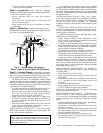
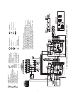
Complete C Control Jumper Settings (See
Fig. 4-6)
WATER COIL FREEZE PROTECTION (FP1) LIMIT
SETTING — Select jumper 3, (JW3-FP1 Low Temp) to
choose FP1 limit of –12.2 C or –1.1 C. To select –1.1 C as the
limit, DO NOT clip the jumper. To select –12.2 C as the limit,
clip the jumper.
ALARM RELAY SETTING — Select jumper 1 (JW1-AL2
Dry) for connecting alarm relay terminal (AL2) to 24 vac (R)
or to remain as a dry contact (no connection). To connect AL2
to R, do not clip the jumper. To set as dry contact, clip the
jumper.
Complete C Control DIP Switches — The
Complete C control has one DIP switch block with five
switches. See Fig. 4-6.
PERFORMANCE MONITOR (PM) — DIP switch 1 will
enable or disable this feature. To enable the PM, set the switch
to ON. To disable the PM, set the switch to OFF.
STAGE 2 — DIP switch 2 will enable or disable compressor
delay. Set DIP switch to OFF for Stage 2 in which the compres-
sor will have a 3-second delay before energizing. DIP switch 3
is not used. DIP switch 4 is not used. DIP switch 5 is used to
initiate one or 3 tries for the FP1 fault. If water freeze protec-
tion for the water coil is needed, then DIP switch 5 can be set to
lock out on the FP1 fault after one try.
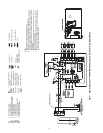
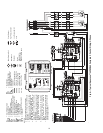
Deluxe D Control Jumper Settings (See
Fig. 7)
WATER COIL FREEZE PROTECTION (FP1) LIMIT
SETTING — Select jumper 3, (JW3-FP1 Low Temp) to
choose FP1 limit of –12.2 C or –1.1 C. To select –1.1 C as the
limit, DO NOT clip the jumper. To select –12.2 C as the limit,
clip the jumper.
ALARM RELAY SETTING — Select jumper 4 (JW4-AL2
Dry) for connecting alarm relay terminal (AL2) to 24 vac (R)
or to remain as a dry contact (no connection). To connect AL2
to R, do not clip the jumper. To set as dry contact, clip the
jumper.
LOW PRESSURE SETTING — The Deluxe D control can
be configured for Low Pressure Setting (LP). Select jumper 1
(JW1-LP Norm Open) for choosing between low pressure in-
put normally opened or closed. To configure for normally
closed operation, do not clip the jumper. To configure for nor-
mally open operation, clip the jumper.
Deluxe D Control DIP Switches — The Deluxe D
control has 2 DIP switch blocks. Each DIP switch block has 8
switches and is labeled either S1 or S2 on the circuit board. See
Fig. 7.
DIP SWITCH BLOCK 1 (S1) — This set of switches offers
the following options for Deluxe D control configuration:
Performance Monitor (PM)
— Set switch 1 to enable or dis-
able performance monitor. To enable the PM, set the switch to
ON. To disable the PM, set the switch to OFF.
Compressor Relay Staging Operation
— Switch 2 will en-
able or disable compressor relay staging operation. The com-
pressor relay can be set to turn on with Stage 1 or Stage 2 call
from the thermostat. This setting is used with dual stage units
(units with 2 compressors and 2 Deluxe D controls) or in mas-
ter/slave applications. In master/slave applications, each com-
pressor and fan will stage according to its switch 2 setting. If
switch is set to Stage 2, the compressor will have a 3-second
delay before energizing during Stage 2 demand.
NOTE: If DIP switch is set for Stage 2, the alarm relay will not
cycle during Test mode.
Heating/Cooling Thermostat Type
— Switch 3 provides selec-
tion of thermostat type. Heat pump or heat/cool thermostats
can be selected. Select OFF for heat/cool thermostats. When in
heat/cool mode, Y1 is used for cooling Stage 1, Y2 is used for
cooling Stage 2, W1 is used for heating Stage 1 and O/W2 is
used for heating Stage 2. Select ON for heat pump applications.
In heat pump mode, Y1 used is for compressor Stage 1, Y2 is
used for compressor Stage 2, W1 is used for heating Stage 3 or
emergency heat, and O/W2 is used for RV (heating or cooling)
depending upon switch 4 setting.
O/B Thermostat Type
— Switch 4 provides selection for heat
pump O/B thermostats. O is cooling output. B is heating out-
put. Select ON for heat pumps with O output. Select OFF for
heat pumps with B output.
Switches 5, 6, 7, 8
— Not used.
DIP SWITCH BLOCK 2 (S2) — Used for accessory relay
configurations.
Deluxe D Control Accessory Relay Configura-
tions (See Tables 4 and 5) —
The following acces-
sory relay settings are applicable for Deluxe D control only:
CYCLE WITH COMPRESSOR — In this configuration, the
relay will be ON any time the compressor relay is on.
DIGITAL NIGHT SETBACK (NSB) — In this configura-
tion, the relay will be ON if the NSB input is connected to
ground C.
NOTE: If there are no relays configured for digital NSB, then
the NSB and OVR inputs are automatically configured for
mechanical operation.
MECHANICAL NIGHT SETBACK — When NSB input is
connected to ground C, all thermostat inputs are ignored. A
thermostat setback heating call will then be connected to the
OVR input. If OVR input becomes active, then the Deluxe D
control will enter night low limit (NLL) staged heating mode.
The NLL staged heating mode will then provide heating during
the NSB period.
WATER VALVE (SLOW OPENING) — If relay is config-
ured for water valve (slow opening), the relay will start 60 sec-
onds prior to starting compressor relay.
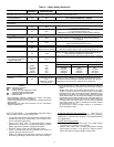
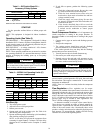
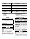
Table 4 — DIP Switch Block S2 —
Accessory 1 Relay Options
LEGEND
NOTE: All other DIP switch combinations are invalid.
IMPORTANT: Jumpers and DIP switches should only
be clipped when power to control board has been turned
off.
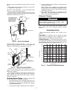
CAUTION
To avoid equipment damage, DO NOT leave system filled
in a building without heat during the winter unless anti-
freeze is added to system water. Condenser coils never
fully drain by themselves and will freeze unless winterized
with antifreeze.
ACCESSORY 1
RELAY OPTIONS
DIP SWITCH POSITION
123
Digital NSB Off On On
Water Valve — Slow Opening On Off On
NSB — Night Setback