


16
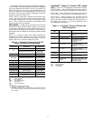
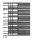
Table 8 — Approximate Fluid Volume (L)
per 30 M of Pipe
LEGEND
NOTE: Volume of heat exchanger is approximately 1.0 gallon
(3.78 liters).
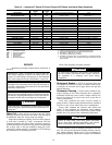
Table 9 — Antifreeze Percentages by Volume
Cooling Tower/Boiler Systems — These systems
typically use a common loop maintained at 15.6 to 32.2 C. The
use of a closed circuit evaporative cooling tower with a second-
ary heat exchanger between the tower and the water loop is rec-
ommended. If an open type cooling tower is used continuously,
chemical treatment and filtering will be necessary.
Ground Coupled, Closed Loop and Plateframe
Heat Exchanger Well Systems — These systems al-
low water temperatures from –1.1 to 43.3 C. The external loop
field is divided up into 51 mm polyethylene supply and return
lines. Each line has valves connected in such a way that upon
system start-up, each line can be isolated for flushing using only
the system pumps. Air separation should be located in the pip-
ing system prior to the fluid re-entering the loop field.
OPERATION
Power Up Mode —
The unit will not operate until all the
inputs, terminals and safety controls are checked for normal
operation.
NOTE: The compressor will have a 5-minute anti-short cycle
upon power up.
Units with Aquazone™ Complete C Control
STANDBY — The Y and W terminals are not active in Stand-
by mode, however the O and G terminals may be active, de-
pending on the application. The compressor will be off.
COOLING — The Y and O terminals are active in Cooling
mode. After power up, the first call to the compressor will initi-
ate a 5 to 80 second random start delay and a 5-minute anti-
short cycle protection time delay. After both delays are com-
plete, the compressor is energized.
NOTE: On all subsequent compressor calls the random start
delay is omitted.
HEATING STAGE 1 — Terminal Y is active in heating
Stage 1. After power up, the first call to the compressor will
initiate a 5 to 80 second random start delay and a 5-minute anti-
short cycle protection time delay. After both delays are
complete, the compressor is energized.
NOTE: On all subsequent compressor calls the random start
delay is omitted.
HEATING STAGE 2 — To enter Stage 2 mode, terminal W is
active (Y is already active). Also, the G terminal must be active
or the W terminal is disregarded.
Units with Aquazone Deluxe D Control
STANDBY — The compressor will be off. The reversing
valve (RV) relays will be on if inputs are present.
HEATING STAGE 1 — In Heating Stage 1 mode, the fan en-
able and compressor relays are turned on immediately. Once
the demand is removed, the relays are turned off and the con-
trol reverts to standby mode. If there is a master/slave or dual
compressor application, all compressor relays and related func-
tions will operate per their associated DIP switch 2 setting on
S1.
HEATING STAGE 2 — In Heating Stage 2 mode, the com-
pressor relays remain on. The control reverts to Heating Stage
1 mode once demand is removed. If there is a master/slave or
dual compressor application, all compressor relays and related
functions will operate per their associated DIP switch 2 setting
on S1.
COOLING STAGE 1 — In Cooling Stage 1 mode, the com-
pressor and RV relays are turned on immediately. If configured
as stage 2 (DIP switch set to OFF) then the compressor and fan
will not turn on until there is a stage 2 demand. The compressor
relays are turned off immediately when the Cooling Stage 1 de-
mand is removed. The control reverts to standby mode. The
RV relay remains on until there is a heating demand. If there is
a master/slave or dual compressor application, all compressor
relays and related functions will track with their associated DIP
switch 2 on S1.
COOLING STAGE 2 — In Cooling Stage 2 mode, the com-
pressor and RV relays remain on. The control reverts to Cool-
ing Stage 1 mode once the demand is removed. If there is a
master/slave or dual compressor application, all compressor re-
lays and related functions will track with their associated DIP
switch 2 on S1.
NIGHT LOW LIMIT (NLL) STAGED HEATING — In NLL
staged heating mode, the override (OVR) input becomes
active and is recognized as a call for heating and the control
will immediately go into a Heating Stage 1 mode. With an
additional 30 minutes of NLL demand, the control will go into
Heating Stage 2 mode. With another additional 30 minutes of
NLL demand, the control will go into Heating Stage 3 mode.
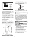
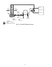
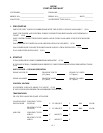
SYSTEM TEST
System testing provides the ability to check the control
operation. The control enters a 20-minute Test mode by mo-
mentarily shorting the test pins. All time delays are increased
15 times. See Fig. 11.
Test Mode — Enter the Test mode on Complete C or
Deluxe D controls by momentarily shorting the test terminals.
The Complete C or Deluxe D control will enter a 20-minute
test mode period in which all time delays are sped up 15 times.
PIPE DIAMETER (in.) [mm] VOLUME (gal.) [L]
Copper 1 [25.4] 4.1 [15.5]
1.25 [31.8] 6.4 [24.2]
1.5 [38.1] 9.2 [34.8]
Rubber Hose 1 [25.4] 3.9 [14.8]
Polyethylene
3
/
4
IPS SDR11 2.8 [10.6]
1 IPS SDR11 4.5 [17.0]
1
1
/
4
IPS SDR11 8.0 [30.8]
1
/
2
IPS SDR11 10.9 [41.3]
2 IPS SDR11 18.0 [68.1]
1
1
/
4
IPS SCH40 8.3 [31.4]
1
1
/
2
IPS SCH40 10.9 [41.3]
2 IPS SCH40 17.0 [64.4]
IPS — Internal Pipe Size
SCH — Schedule
SDR — Standard Dimensional Ratio
ANTIFREEZE
MINIMUM TEMPERATURE FOR FREEZE
PROTECTION (C)
–12.2 –9.4 –6.7 –3.9
Methanol (%) 25 21 16 10
100% USP Food Grade
Propylene Glycol (%)
38 30 22 15
Ethanol (%) 29 25 20 14
C
R
R
C
CC
CCG
BR
BRG
Test
Off On
FP1JW3
TEST
MODE
PINS
Fig. 11 — Test Mode Pins Location