


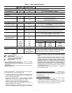

10
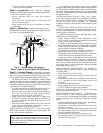
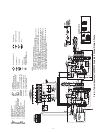
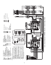
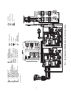
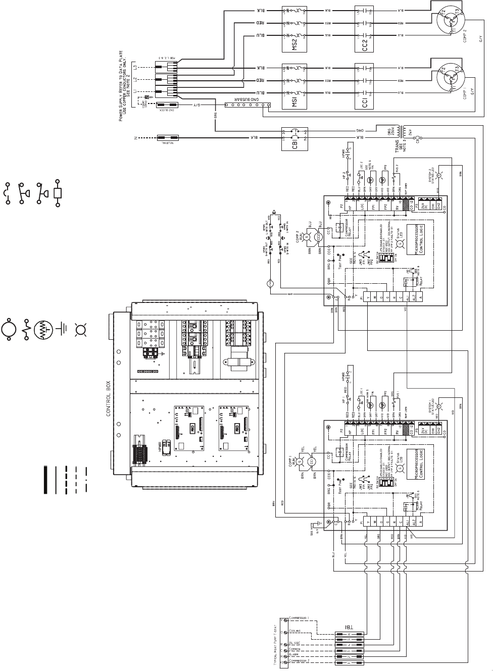
Fig. 6 — Typical Aquazone™ 50PSW360 Complete C Control Wiring, 3-Phase
Circuit Breaker
High Pressure Switch
Low Pressure Switch
Fuse
F
Complete C
Complete C 1
Complete C 2
Complete C
6
NOTES:
1. Compressor thermally protected internally.
2. All wiring to the unit must comply with NEC and
local codes.
3. Transformer is wired to 380 v lead (VIO) for 380-
3-50 operation. For 420 v operation switch VIO
and BRN leads at L1 and insulate VIO lead.
4. FP1 thermistor provides freeze protection for
source water. When using antifreeze solutions,
cut JW3 jumper.
5. Check installation wiring information for controller
hookup. Control wiring must be Class 1 and volt-
age rating equal to or greater than unit supply
voltage.
6. Transformer secondary ground via Complete C
board standoff and screws to control box.
(Ground available from top 2 standoffs as
shown.)
7. Aquastat is supplied with unit and must be wired
in series with the hot leg of the pump. Aquastat is
rated for voltages up to 277 v.
MS — Motor Switch
NEC — National Electrical Code
P1 — Field Wiring Terminal Block
RVS — Reversing Valve Solenoid
S-WTR — Source Water
TRANS — Transformer
Factory Line Voltage Wiring
Factory Low Voltage Wiring
Field Line Voltage Wiring
Field Low Voltage Wiring
Printed Circuit Trace
AL — Alarm Relay Contacts
ASTAT — Aquastat Device
COMP — Compressor
CC — Compressor Contactor
DTS — Discharge Temperature Switch
FP1 — Sensor, Source Low Temp Protection
FP2 — Sensor, Load Low Temp Protection
HP — High Pressure Switch
HPWS — High Pressure Water Switch
HWG — Hot Water Generator
JW1 — Jumper Wire for Alarm
LED — Light Emitting Diode
LOC — Loss of Charge Pressure Switch
L-WTR — Load Water
Relay/Contactor Coil
Solenoid Coil
Thermistor
Ground
Indicator Light
G=Green, R=Red
(Comp On) (Alarm Light)