


4
PROTECTION — Once the units are properly positioned on
the jobsite, they must be covered with either a shipping carton,
vinyl film, or an equivalent protective covering. Open ends of
pipes stored on the jobsite must be capped. This precaution is
especially important in areas where painting, plastering, or
spraying of fireproof material, etc., is not yet complete. Foreign
material that is allowed to accumulate within the units can pre-
vent proper start-up and necessitate costly clean-up operations.
Before installing any of the system components, be sure to
examine each pipe, fitting, and valve, and remove any dirt or
foreign material found in or on these components.
INSPECT UNIT — To prepare the unit for installation, com-
plete the procedures listed below:
1. Compare the electrical data on the unit nameplate with
ordering and shipping information to verify that the
correct unit has been shipped.
2. Verify that the unit is the correct model for the entering
water temperature of the job.
3. Wait to remove the packaging until the unit is ready for
installation.
4. Verify that the refrigerant tubing is free of kinks or dents,
and that it does not touch other unit components.
5. Inspect all electrical connections. Be sure connections are
clean and tight at the terminals.
6. Loosen bolts and remove shipping clamps on compres-
sors equipped with external spring vibration isolators.
Compressors are internally spring-mounted.
7. Locate and verify any accessory kit located in compressor
section.
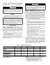
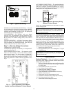
31.338.1 11.4
10.8
Power Supply Wiring
34.9 x 50.8 mm Double Knockout
10.8
Control Wiring
28.6 x 34.9 mm Double Knockout
11.4
2” FPT Water Connections
38.1
13.8
53.3
Fault/Run Lights
163.8
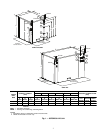
Left
Side
View
Front
View
Top
View
Load
Source
Side
Refrig.
Circuit
Access
Panel
Front
Compressor
Access
Panel
Electrical
Access
Panel
Header
Access
Panel
Top
Minimum91cm
Required Service
Access
114.6
66.9
Optional (Single Unit)
91cm Additional
Service Access
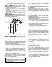
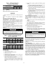
Fig. 2 — 50PSW180,360 Unit
LEGEND
FPT — Female Pipe Thread
NOTES:
1. Dimensions shown in centimeters unless noted other-
wise.
2. For multiple units placed side by side, allow 1.2 m mini-
mum front access for service and maintenance.
CAUTION
DO NOT store or install units in corrosive environments or
in locations subject to temperature or humidity extremes
(e.g., attics, garages, rooftops, etc.). Corrosive conditions
and high temperature or humidity can significantly reduce
performance, reliability, and service life. Always move
units in an upright position. Tilting units on their sides may
cause equipment damage.