


73
Carrier Comfort Network
®
(CCN) Interface —
The 48P Series units can be connected to the CCN system if
desired. The communication bus wiring is supplied and
installed in the field. It consists of shielded, 3-conductor cable
with shield wire.
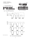
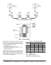
The system elements are connected to the communication
bus in a daisy chain arrangement. The positive pin of each
system element communication connector must be wired to the
positive pins of the system element on either side of it, the
negative pins must be wired to the negative pins, and the signal
pins must be wired to common pins. Wiring connections for
the CCN system should be made at the terminal block using the
screw terminals. The board also contains an RJ14 CCN plug
that can be used to connect a field service computer. There is
also another RJ14 LEN (Local Equipment Network) connec-
tion that is used to download software or connect a Naviga-
tor™ device.
NOTE: Conductors and drain wire must be 20 AWG minimum
stranded, tinned copper. Individual conductors must be insu-
lated with PVC, PVC/nylon, vinyl, Teflon, or polyethylene. An
aluminum/polyester 100% foil shield and an outer jacket of
PVC, PVC/nylon, chrome vinyl, or Teflon with a minimum
operating temperature range of –4 to 140 F (–20 C to 60 C) is
required. See Table 28 for cables that meet the requirements.
Table 28 — CCN Connection Approved
Shielded Cables
The following color code is recommended:
NOTE: If a cable with a different color scheme is selected, a
similar color code should be adopted for the entire network.
At each system element, the shields of its communication
bus cables must be tied together. If the communication bus is
entirely within one building, the resulting continuous field
must be connected to a ground at one point only. If the commu-
nication bus cable exits from one building and enters another,
the shields must be connected to grounds at the lightning
suppressor in each building where the cable enters or exits the
building (one point per building only).
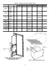
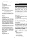
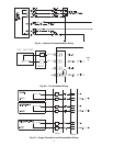
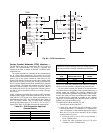
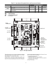
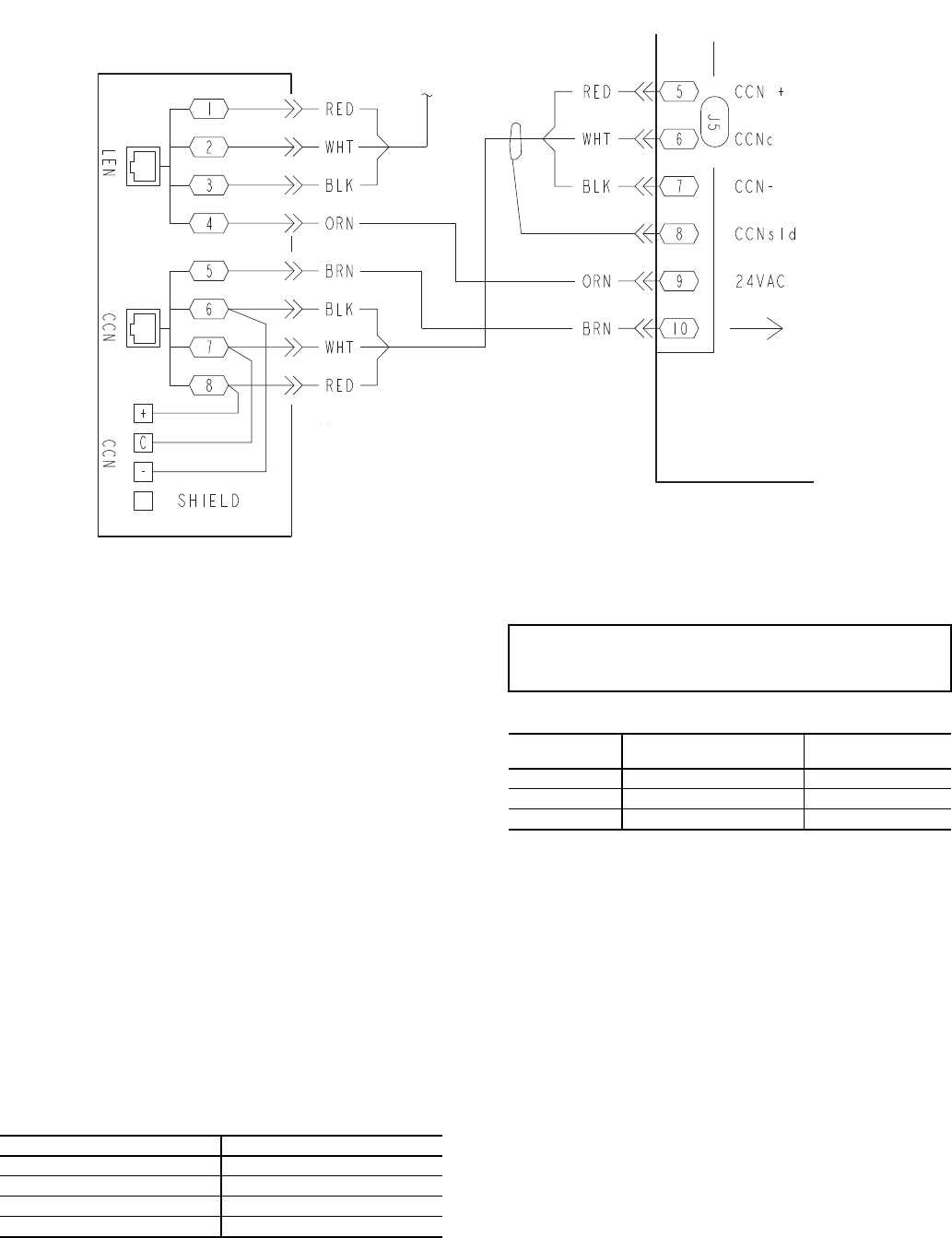
To connect the unit to the network (Fig. 84):
1. Turn off power to the control box.
2. Cut the CCN wire and strip the ends of the red (+), white
(common) and black (–) conductors. (If a different net-
work color scheme is used, substitute appropriate colors.)
3. Wire the CCN to the screw terminals on the COMM
board as follows (Fig. 84):
a. Secure the red (+) wire to CCN screw terminal +
on the COMM board.
b. Secure the white (common) wire to CCN screw
terminal C on the COMM board.
TB201
MBB
J5
Fig. 84 — CCN Connections
a48-8487
MANUFACTURER CABLE PART NO.
Alpha 2413 or 5463
American A22503
Belden 8772
Columbia 02525
IMPORTANT: When connecting the CCN communica-
tion bus to a system element, use a color coding system for
the entire network to simplify installation and checkout.
SIGNAL
TYPE
CCN BUS CONDUCTOR
INSULATION COLOR
COMM1 PLUG
PIN NO.
+ RED 1
COMMON WHITE 2
– BLACK 3