


32
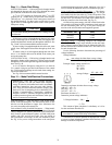
Step 9 — Install Outdoor Hoods (Units without
Optional High-Capacity Power Exhaust)
UNIT SIZES 030-050
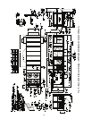
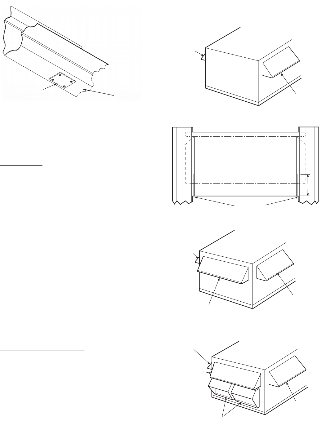
25% Outdoor-Air Hoods (Units without Economizer
Option) (Fig. 28)
1. Outdoor-air hoods are shipped bolted to the unit in a ship-
ping position. Remove the 6 screws holding each 25%
outdoor air hood shipping cover in place.
2. Remove the holddown screw from each upper corner of
each hood.
3. Pivot hoods outward (2 hoods).
4. Install 17 screws around outside of each hood. (Screws
are in the fastener package taped to the basepan inside the
fan section.)
5. Apply a bead of RTV or similar sealant to corner of each
hood at pivot points to prevent water leaks. See Fig. 29.
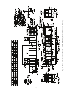
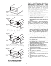
Economizer Hoods (Units with Economizer Option)
(Fig. 30 and 31)
1. Remove the 4 screws holding each of the 2 economizer
side hoods in place.
2. Pivot hoods outwards (2 hoods).
3. Apply seal strip to vertical flange of hood sides.
4. Install hood sides of hood top using 19 screws (7 each
side, 5 top). Screws are in fastener package located with
the hood sides and seal strip which is taped inside the
unit.
5. Apply a bead of RTV or similar sealant to corners of
economizer hoods at pivot points to prevent water leaks.
See Fig. 29.
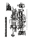
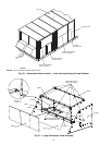
UNIT SIZES 055-100
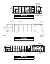
25% Outdoor-Air Hoods (Fig. 32)
— The outdoor-air hoods
are factory installed on the 055-100 units.
Economizer Hoods (Units with Economizer Option) (Fig. 33-35)
1. Remove the 6 screws holding each of the 4 economizer
shipping covers in place.
2. Remove the holddown screw from each upper corner of
each economizer hood.
3. Pivot hoods outward (4 hoods).
4. Apply seal strip to vertical flange of hood sides.
5. Install 18 screws (5 each side, 6 top, and 2 bottom)
around the outside of each hood. (Screws are in the fas-
tener package taped to the basepan inside the fan section.)
6. Apply a bead of RTV or similar sealant to corner of econ-
omizer hood at pivot points to prevent water leaks. See
Fig. 29.
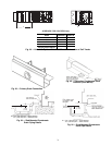
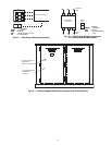
16-GAGE METAL
SEAL PLATE
(FIELD SUPPLIED
FIELD INSTALLED)
BOTTOM OF
BASE RAIL
Fig. 27 — Secondary Drain Seal Plate
Location (Slab Mount)
a48-8459
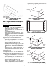
RTV
(ALL HOODS)
4”
OUTDOOR-AIR HOOD
Fig. 29 — Outdoor-Air and Economizer Hood
OUTDOOR
AIR HOOD
OUTDOOR
AIR HOOD
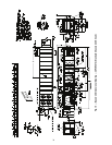
Fig. 28 — Outdoor Air Hood Installation
(Sizes 030-050)
SIDE HOOD
(ROTATE
OPEN)
SIDE HOOD
(ROTATE
OPEN)
END HOOD
(FIXED)
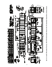
Fig. 30 — Economizer Outdoor-Air Hood
Installation (Sizes 030-050)
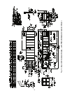
POWER EXHAUST (FIXED)
SIDE HOOD
(ROTATE
OPEN)
SIDE HOOD
(ROTATE
OPEN)
END HOOD
(FIXED)
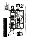
Fig. 31 — Economizer with Power Exhaust
Outdoor-Air Hood Installation (Sizes 030-050)
a48-8461