


62
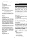
Step 18 — Install Flue/Inlet Hoods and
Baffles — The flue/inlet hoods and baffles are shipped in a
package taped to the basepan in the fan section. The flue (out-
let) hoods are pre-assembled. The flue deflector, inlet hoods,
and baffles require assembly.
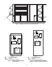
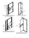
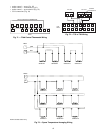
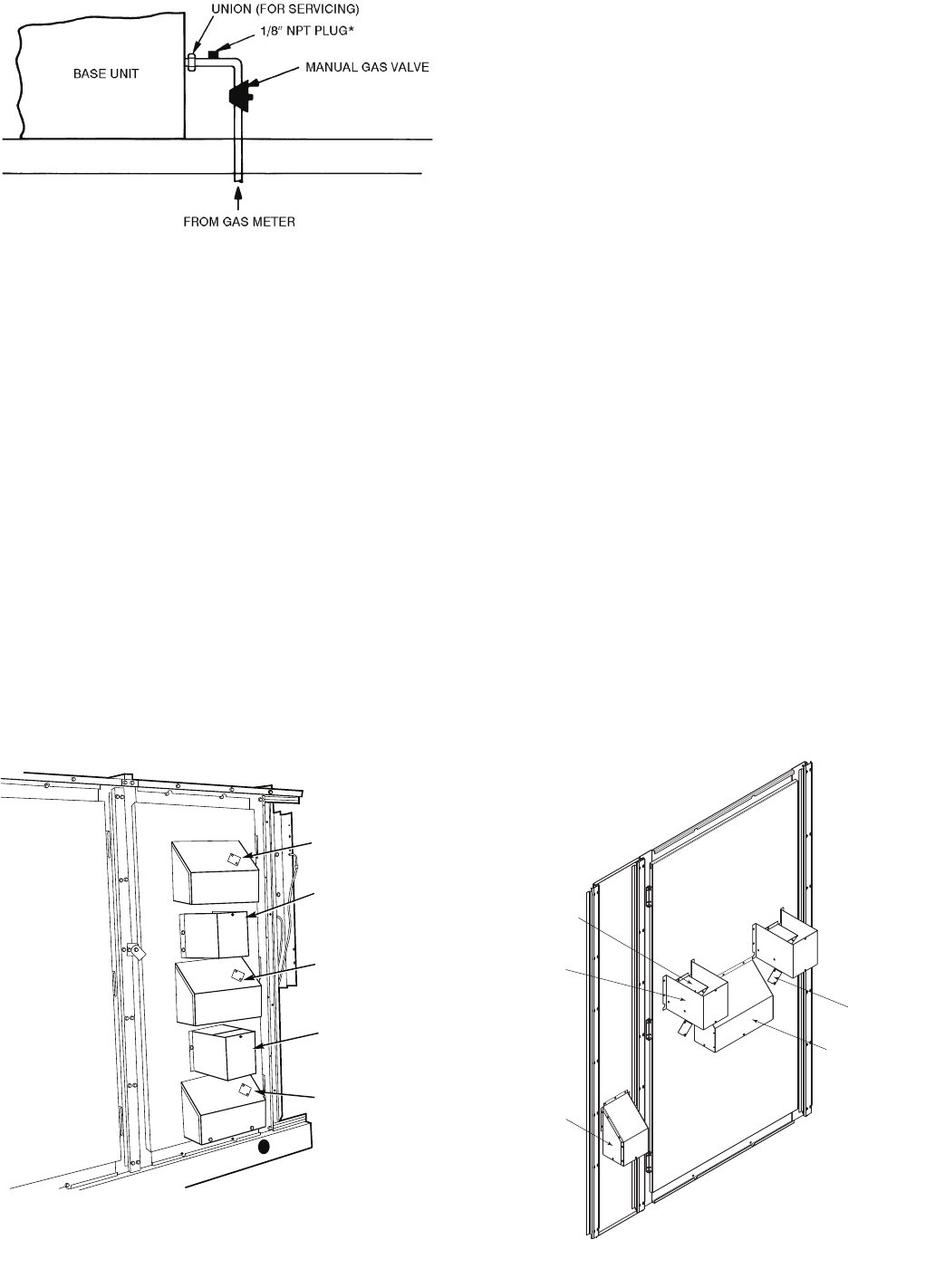
The hoods are located on the heating section access panel as
shown in Fig. 54 (sizes 030-050), Fig. 55 (sizes 055-100 with
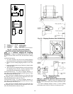
low heat and vertical supply), Fig. 56 (sizes 055-100 with low
heat and horizontal supply), and Fig. 57 (sizes 055-100 with
high heat). The inlet baffles are located inside the access panel
as illustrated in Fig. 58 (sizes 030-050), Fig. 59 (sizes 055-100
with modulating low heat and horizontal supply), and Fig. 60
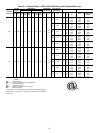
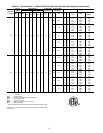
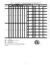
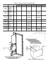
(sizes 055-100 with modulating high heat). See Table 26 for a
list of parts used to assemble each hood and quantities of each
hood type and baffle used with each unit.
1. Remove shipping block-offs and shipping tape from all
openings in the access panel.
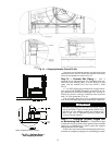
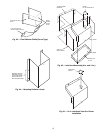
2. Attach flue outlet hoods (see Fig. 61) to access panel us-
ing screws provided. Hoods are placed over each com-
bustion outlet.
3. Install flue deflector baffle inside flue deflector hood. See
Fig 62 for V-type deflector and Fig. 63 for curve-type
deflector. For V-type deflector, screw the baffle and hood
together with screw provided. Refer to Table 26 for
usage.
4. Install flue deflector hood assembly over each flue outlet
hood. See Fig. 64. Observe the offset mounting hole loca-
tions in the deflector hood flanges when attaching hood to
panel. Holes in the mounting flange must be at the bottom
when attached.
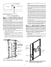
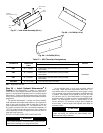
5. Inlet hoods are shipped unassembled and must be assem-
bled on the access panel (see Fig. 65-67). Flanges of the
hood top and sides should be installed on the inside of the
access panel openings with the screws provided. The
sides should be placed on the inside of top hoods for all
hood assemblies (6-in., 14-in., and 30-in.). Attach speed
clips to screen. Insert screen into bottom opening of 6-in.
and 14-in. hoods and secure it with 3 screws. To ease the
installation, the 30-in. hood screen may be inserted from
inside of access panel (gas section door) into bottom
opening of hood. Secure with 5 screws. Attached view
port cover over 14-in. inlet hood opening (Fig. 66). Se-
cure with two screws.
6. Install inlet baffle on the access panel with the screw(s)
provided. See Fig. 68 for 14-in baffle and Fig. 69 for
30-in baffle. Attach 14-in baffle from the outside of the
access panel. The 30-in baffle should be installed from in-
side of the access panel. Secure with three screws.
Step 19 — Install Supply-Air Thermistors
(Staged and Modulating Gas Units Only) —
Supply-air thermistors are a field-installed, factory-provided
component. Three supply-air thermistors are shipped with
staged and modulating gas units inside the unit control box.
Thermistor wires must be connected to the SGC in the unit
control box. See Table 27. The supply-air thermistors should
be located in the supply duct with the following criteria:
• downstream of the heat exchanger cells
• equally spaced as far as possible from the heat
exchanger cells
• a duct location where none of the supply air thermistors
are within sight of the heat exchanger cells
• a duct location with good mixed supply air portion of the
unit.
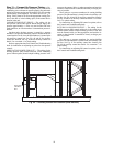
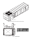
*NPT plug is field supplied.
NOTE: Follow all local codes.
Fig. 53 — Gas Piping Details
FLUE OUTLET
HOOD
FLUE HOOD
AND FLUE
DEFLECTOR
HOOD
6-IN. INLET
HOOD
14-IN. INLET
HOOD
VIEW PORT
COVER
FLUE HOOD AND
FLUE DEFLECTOR
HOOD (48 SERIES
HIGH-HEAT ONLY)
INLET HOOD
FLUE HOOD AND
DEFLECTOR
HOOD
INLET HOOD
INLET HOOD
14-IN.
14-IN.
14-IN.
Fig. 54 — Flue/Inlet Hood Locations, 030-050 Units
Fig. 55 — Flue/Inlet Hood Locations, Sizes 055-100,
Low Heat, Vertical Supply Units
a48-8469
a48-8470