


35
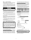
Step 11 — Route Field Wiring
UNIT SIZES 030-060 — Field wiring can be brought into the
unit through the basepan and roof curb or through the corner
post in the side of the unit next to the control box.
A 3
1
/
2
-in. FPT coupling for field power and a
3
/
4
-in. FPT
coupling for 24 v control wiring are provided in the basepan.
There are two
7
/
8
-in. pilot holes in the corner post as shown on
the certified drawings. Use these holes as pilot holes for mak-
ing the hole for field-supplied conduit in the corner post for
field power wiring.
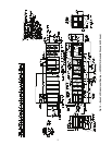
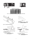
If field power wiring is brought through the roof curb, route
wiring out through one of the holes to the field-supplied dis-
connect and then back into the unit through the other hole. See
Fig. 38 and 39 for recommended disconnect location.
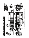
If power wiring is brought through the side of the unit, route
wiring from field-supplied disconnect through top hole into
unit.
If control wiring is to be brought in through the side of the
unit, a
7
/
8
-in. diameter hole must be drilled in the corner post
next to the control box.
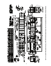
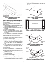
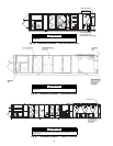
UNIT SIZES 070-100 — Field wiring is brought into the unit
through the bottom of the control box. Wiring can be brought
through the roof curb through field-supplied watertight connec-
tions. See Fig. 40.
A 4
5
/
32
-in. hole for field power wiring and a
7
/
8
-in. hole for
24 v control wiring are provided in the bottom of the control
box. Field-supplied couplings must be used when routing wir-
ing into the control box.
See Fig. 40 for recommended disconnect location.
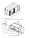
Step 12 — Make Field Electrical Connections
POWER WIRING — Units are factory wired for the voltage
shown on the unit nameplate. The main terminal block is suit-
able for use with aluminum or copper wires. Maximum wire
size varies according to disconnect size.
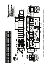
Units without Factory-Installed Disconnect
— When install-
ing units, provide a disconnect per NEC (National Electrical
Code) of adequate size (MOCP [maximum overcurrent protec-
tion] of unit is on the informative plate). All field wiring must
comply with NEC and all local codes. Size wire based on
MCA (minimum circuit amps) on the unit informative plate.
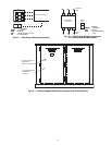
See Fig. 41 for power wiring connections to the unit power
terminal block and equipment ground. Maximum wire size is
two (2) 500 MCM (maximum wire size) conductors per pole.
Units with Factory-Installed Disconnect
— The factory-
installed disconnect is an interlocking, door-type. The discon-
nect handle locks the door when it is in the ON position. The
disconnect handle must be in the OFF position to open the con-
trol box door. The disconnect is located in the control box be-
hind the control box door for all units. See Fig. 42.
All field wiring must comply with NEC and all local codes.
Wire must be sized based on MCA (minimum circuit amps) on
the unit informative plate. See Fig. 43 for power wiring con-
nections to the unit disconnect and equipment ground.
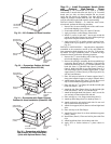
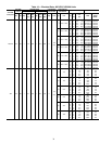
Operating Voltage
— Operating voltage to the compressor
must be within the voltage range indicated on the unit name-
plate. Voltages between phases must be balanced within 2%,
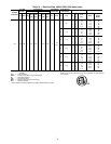
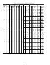
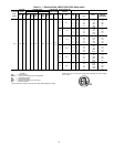
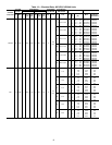
and the current must be balanced within 10%. See Tables 10-25
for unit electrical data.
Use the following formula to determine the percentage of
voltage imbalance.
Voltage Imbalance
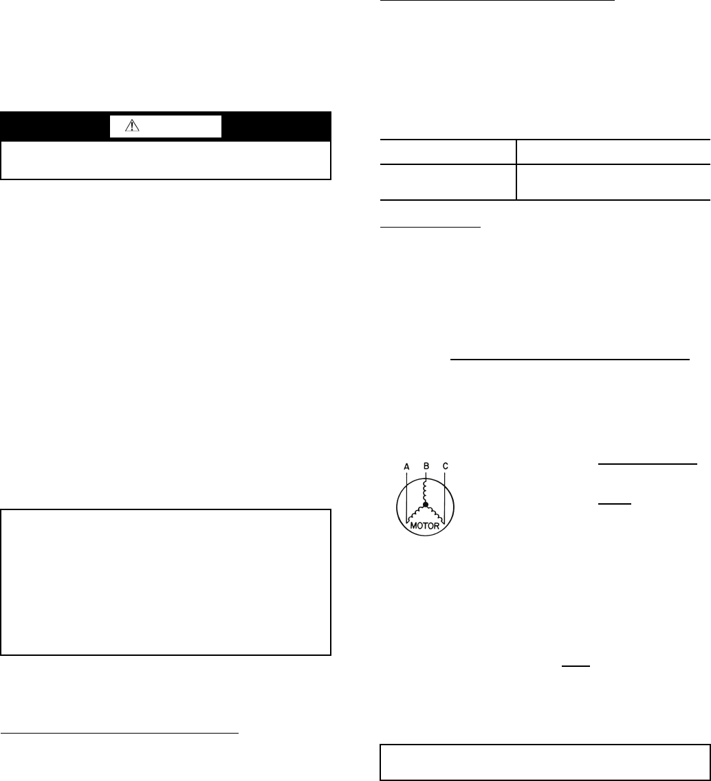
Example: Supply voltage is 460-3-60.
AB = 452 v
BC = 464 v
AC = 455 v
Determine maximum deviation from average voltage:
(AB) 457 – 452 = 5 v
(BC) 464 – 457 = 7 v
(AC) 457 – 455 = 2 v
Maximum deviation is 7 v.
Determine percent voltage imbalance:
= 1.53%
This amount of phase imbalance is satisfactory as it is be-
low the maximum allowable 2%.
Unit failure as a result of operation on improper line voltage
or excessive phase imbalance constitutes abuse and may cause
damage to electrical components.
CAUTION
Use care when drilling near condenser coil. Damage to unit
could result.
IMPORTANT: Units with VFDs (variable frequency
drives) generate, use, and can radiate radio frequency
energy. If units are not installed and used in accordance
with these instructions, they may cause radio interfer-
ence. They have been tested and found to comply with
limits of a Class A computing device as defined by FCC
(Federal Communications Commission) regulations,
Subpart J of Part 15, which are designed to provide rea-
sonable protection against such interference when oper-
ated in a commercial environment.
DISCONNECT SIZE
QUANTITY...MAXIMUM WIRE SIZE
(MCM)
250 Amps
400 Amps
600 Amps
1...300
1...600
2...600
= 100 x
max voltage deviation from average voltage
average voltage
Average Voltage =
455 + 464 + 455
3
=
1371
3
= 457
% Voltage Imbalance = 100 x
7
457
IMPORTANT: If the supply voltage phase imbalance is
more than 2%, contact local utility immediately.