


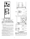

68
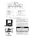
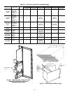
Step 21 — Install Unit Accessories — For appli-
cations requiring accessories, the following packages are
available:
All units:
• barometric relief
• space temperature sensor
•CO
2
sensor
• space temperature sensor with CO
2
sensor
• airflow switch
• filter switch
• smoke detector
All 48P2,P4 (constant volume) units:
• modulating power exhaust
All 48P3,P5 (variable air volume) units:
• modulating power exhaust
Refer to the individual accessory installation instructions in
each accessory package for information on installing accessories.
CONTROLS INSTALLATION
Constant Volume (CV) Units —
The 48P2,P4 units
may be used in applications with additional control features,
options, or accessories. Refer to the appropriate accessory
installation instructions for more information on installing that
accessory. Control options and accessories available for CV
units are:
• thermostats
• enthalpy sensor
• enthalpy switch
• relative humidity sensor
• CEM (controls expansion module)
• Navigator™ hand-held display
CONTROL WIRING — The unit can be controlled with a
Carrier-approved accessory electro-mechanical or electronic
thermostat that has two stages of cooling, two stages of heating
control, and an output for fan control. The thermostat may also
include time of day scheduling or use scheduling routines built
into the ComfortLink™ controls.
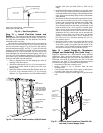
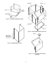
Install the thermostat according to the installation instruc-
tions shipped with the accessory thermostat. Locate thermostat
assembly on a solid interior wall to sense average temperature.
Route thermostat cable or equivalent leads of colored wire
from subbase terminals through conduit into the low voltage
connections in the main control box. For thermostat TB201
connections, see Fig. 71.
NOTE: For wire runs up to 50 ft, use no. 18 AWG (American
Wire Gage) insulated wire (35 C minimum). For over 75 ft, use
no. 14 AWG insulated wire (35 C minimum). All wire larger
than no. 18 AWG cannot be directly connected at the thermostat
and will require a junction box and splice at the thermostat.
Variable Air Volume (VAV) Units — The 48P3,P5
units may be used in applications with additional control fea-
tures, options, or accessories. Refer to the appropriate accesso-
ry installation instructions for more information on installing
that accessory. Refer to the Controls and Troubleshooting man-
ual for more information concerning installation and configura-
tion of options and accessories. Control options and accessories
available for VAV units are:
• enthalpy sensor
• enthalpy switch
• relative humidity sensor
• CEM (controls expansion module)
• Navigator hand-held display
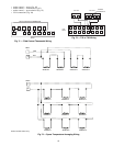
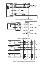
VAV CONTROL WIRING — The recommended types of
control wiring are shown below:
SENSORS — Sensors should be wired using single twisted
pairs of 20 AWG (American Wire Gage) conductor cable rated
for the application, except for the T-56 accessory sensor which
requires 3-conductor cable.
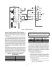
HUMIDITY CONTROL AND HOT WATER AND
STEAM VALVES — These devices require 20 AWG twisted
pair conductor cables rated for the application for the 4 to
20 mA signal.
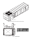
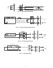
SPACE TEMPERATURE SENSOR (T-55) — The space tem-
perature sensor (P/N 33ZCT55SPT), if used, is wired to termi-
nals in the unit main control box. To connect the space temper-
ature sensor, see Fig. 72.
SPACE TEMPERATURE SENSOR (T-56) — The space tem-
perature sensor (P/N 33ZCT56SPT), if used, is wired to termi-
nals in the unit main control box. To connect the space temper-
ature sensor, see Fig. 72.
COMMUNICATING SPACE TEMPERATURE SENSOR
(T-58) — The communicating space temperature sensor (P/N
33ZCT58SPT) is wired to the Carrier Comfort Network
®
(CCN) connections on TB202.
SPACE TEMPERATURE AVERAGING — Applications that
require averaging using multiple space temperature sensors can
be satisfied using either 4 or 9 sensors as shown in Fig. 73.
NOTE: Only Carrier sensors may be used for standard T-55
space averaging. Sensors must be used in multiples of 1, 4, and
9 only, with total sensors wiring not to exceed 1000 ft.
NOTE: Do not use T-56 sensors for space temperature averag-
ing because the 5-degree offset function will not work in a
multiple sensor application.
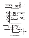
HEAT INTERLOCK RELAY (VAV Units Only — Not Neces-
sary for Digital Air Volume Applications) — Variable air vol-
ume (VAV) units using morning warm-up and/or occupied
heating require that room terminals be controlled to a position
that provides the minimum required heating cfm or greater
when the unit goes into Heating mode. The HIR (heat interlock
relay) function is provided for this control. When the unit goes
into Heating mode, the HIR is energized to provide switch clo-
sure or opening (depending on how the field-supplied power
source is set up) to open the room terminals. The field connec-
tions for the HIR are at TB201 terminals 9 and 10. See Fig. 74.
Option and Accessory Control Wiring — The P
Series units may be used in applications with additional control
features, options, or accessories. Refer to the Controls and
Troubleshooting manual for more information concerning
installation and configuration of options and accessories.
Figures 74-84 contain wiring information on the following
features:
• heat interlock relay (Fig. 74)
• outdoor air enthalpy switch (Fig. 75)
•CO
2
space sensor (Fig. 76)
• filter status switch (Fig. 77)
• fan status switch (Fig. 78)
• space humidity sensor (Fig. 79)
• return air humidity sensor (Fig. 79)
• return air CO
2
sensor (Fig. 80)
• return air smoke detector (Fig. 81)
• smoke control — fire shutdown (Fig. 82)
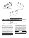
MANUFACTURER
PART NO.
Regular Wiring Plenum Wiring
Alpha 1895 —
American A21451 A48301
Belden 8205 884421
Columbia D6451 —
Manhattan M13402 M64430
Quabik 6130 —