


61
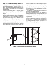
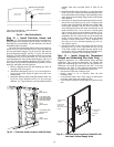
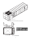
After removing all shipping brackets, level the fan using the
adjustment screws. On all 4 corners the dimension from cross
rail to fan sled should be as shown in Fig. 52.
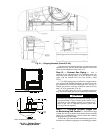
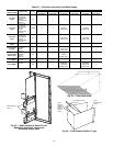
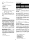
Step 16 — Connect Gas Piping — Unit is
equipped for use with natural gas only. Installation must con-
form with local building codes, or in the absence of local
codes, with the National Fuel Gas Code (NFGC), ANSI
Z223.1.
A
1
/
8
-in. NPT tapping plug, accessible for test gage connec-
tion, must be field installed immediately upstream of gas sup-
ply connection to unit, but after manual gas valve. See Fig. 53.
Natural gas pressure at unit gas connection must not be less
than 5 in. wg or greater than 13 in. wg.
Size gas supply piping for 0.5 in. wg maximum pressure
drop. Do not use supply pipe smaller than unit gas connection.
Step 17 — Configure Optional Staged Gas
or Modulating Gas Control —
The 48P Series large
rooftop units may be ordered with an optional factory-installed
staged gas or modulating gas control system that monitors
heating operation of the rooftop.
Refer to the Unit Controls and Troubleshooting book for in-
formation on configuring staged gas or modulating gas control.
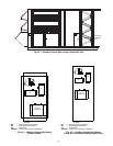
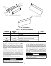
Fig. 51 — Shipping Brackets (Sizes 075-100)
a48-8468
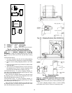
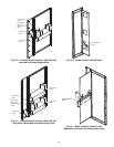
Fig. 52 — Optional Return
Fan Shipping Brackets
NOTE: All dimensions are in inches.
CAUTION
Disconnect gas piping from unit when leak testing at pres-
sures greater than 0.5 psig. Pressures greater than 0.5 psig
will cause gas valve damage resulting in a hazardous con-
dition. If gas valve is subjected to pressure greater than
0.5 psig, it must be replaced.