


20
Locate the four 1
1
/
4
-in. drain coupling assemblies and
mounting screws (shipped in a bag taped to the basepan in the
supply fan section, located behind the access panel marked
FAN SECTION). The drain couplings are a 10-gage plate with
a 1
1
/
4
in. half coupling welded to the plate.
After final positioning of the unit, perform the following
procedure:
1. At each of the four secondary drain locations (marked
with labels on the unit base rail), position the drain cou-
pling assembly in the side of the base rail. Mark the
screw holes and the drain hole locations on the base rail.
2. Drill holes for drain outlet (use 1
3
/
8
-in. hole saw) and for
the mounting screws (use
3
/
16
-in. drill bit).
3. Install a drain coupling assembly using screws provided
at each secondary drain hole location.
4. Using field-supplied fittings and pipe sections, assemble
U-traps at each secondary drain fitting. See Fig. 24. Pro-
vide minimum size of ½-in. pipe for secondary drains.
Use a trap at least 4-in. deep for size 030-070 units and
7-in. deep for size 075-100 units.
5. Apply a bead of RTV or similar sealant around the drain
assemblies.
Consult local plumbing codes for direction on joining multi-
ple drain lines. Total size of any combined line does not need to
exceed nominal 2-in. size of primary drain connection.
Fill the U-traps at the secondary drain locations prior to unit
start-up. Also check the U-traps before each cooling season to
ensure the traps are filled and functioning properly.
3
2
A
B
4
1
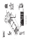
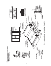
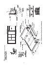
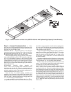
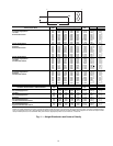
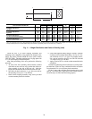
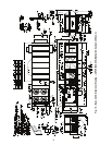
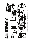
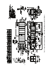
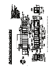
NOTE: The weight distribution and center of gravity information include the impact of an economizer, the largest indoor fan motor, and a VFD (variable frequency
drive). On units with a return fan or high-capacity power exhaust, the largest motors and VFD are also included. These weights do not include the impact of other
factory-installed options such as barometric relief, power exhaust, high-capacity indoor coil, hot water coil, or indoor fan.
48P2,P3,P4,P5 UNITS
WITH OPTIONAL RETURN FAN
SIZE
CORNER WEIGHTS (lb)
TOTAL
(lb)
AB
1234 in. in.
Vertical Supply/Return
Horizontal Supply/Return
Low Heat
075 3470 3449 2693 2709 12,321 224
5
/
8
40
1
/
4
090 3327 3745 3097 2751 12,921 232
5
/
8
41
1
/
2
100
3302 3782 3127 2730 12,941 230
3
/
8
41
1
/
2
Vertical Supply/Return
Horizontal Supply/Return
High Heat
075 3543 3449 2693 2766 12,451 226
7
/
8
40
1
/
4
090 3377 3767 3115 2793 13,051 233
3
/
4
41
1
/
2
100
3370 3785 3130 2787 13,071 232
7
/
8
41
1
/
2
Vertical Supply/Return
Horizontal Supply/Return
Low Heat with Extended Chassis
075 3609 3618 2825 2818 12,871 236
1
/
4
40
1
/
4
090 3467 3906 3230 2867 13,471 244
1
/
4
41
1
/
2
100
3437 3948 3264 2842 13,491 241
3
/
4
41
1
/
2
Vertical Supply/Return
Horizontal Supply/Return
High Heat with Extended Chassis
075 3681 3620 2826 2874 13,001 238
1
/
2
40
1
/
4
090 3517 3928 3248 2908 13,601 245
3
/
8
41
1
/
2
100
3505 3951 3267 2898 13,621 244
1
/
4
41
1
/
2
Fig. 11 — Weight Distribution and Center of Gravity (cont)