


16
Step 8 — Connect Condensate Drain — There
are a total of five drain connections required on each unit: one
primary drain (on right-hand side of the unit) and four second-
ary drains (two on each side of unit).
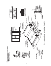
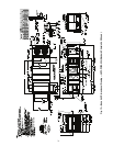
PRIMARY DRAIN — The primary drain is a 2-in. FPT pipe
connection located on the right-hand side of the unit looking at
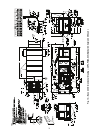
the unit from the return air end. See Fig. 12-21. Fig. 22 shows
the additional length of units with an extended chassis.
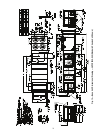
With field-supplied fittings and pipe sections, plumb the pri-
mary condensate drain to the 2-in. FPT connector on the base
rail. Use a trap height of at least 4-in. for size 030-070 units
and 7-in. for size 075-100 units. See Fig. 23 and 24. Install with
a height dimension of at least 2-in. from the top of the exit pipe
from the trap section to the bottom of the connector. Apply a
bead of RTV or similar sealant around the pipe joint at the con-
nector in the base rail.
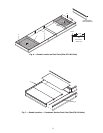
SECONDARY DRAINS (Units Installed on
Curb) — There are two secondary drain connections on each
side of the unit. See Fig. 25. There are secondary drains on
each side of the unit in the filter section and on each side of the
unit in the supply fan section. There are labels marking each lo-
cation on the unit base rail. See Fig. 12-21.
Locate the four 1
1
/
4
-in. drain coupling assemblies and
mounting screws (shipped in a bag taped to the basepan in the
supply fan section, located behind the access panel marked
FAN SECTION). The drain couplings are a 10-gage plate with
a 1
1
/
4
in. half coupling welded to the plate.
At each secondary drain hole location, there is a 1
3
/
8
-in.
hole pre-drilled in the bottom of the base rail, surrounded by
four 0.20-in. engagement holes. Install a drain coupling assem-
bly using screws provided at each secondary drain hole loca-
tion. See Fig. 26. Do not attach any drain coupling assemblies
in the condenser section base rail.
Using field-supplied fittings and pipe sections, assemble U-
traps at each secondary drain fitting. See Fig. 27. Provide a
minimum size of ½-in. pipe for secondary drains. Use a trap at
least 4-in. deep for size 030-070 units and 7-in. deep for size
075-100 units. Apply a bead of RTV or similar sealant around
the drain assemblies.
Consult local plumbing codes for direction on joining multi-
ple drain lines. Total size of any combined line does not need
to exceed nominal 2-in. size of primary drain connection.
Fill the U-traps at the secondary drain locations prior to unit
start-up. Also check the U-traps before each cooling season to
ensure the traps are filled and functioning properly.
SECONDARY DRAINS (Units Installed on Steel Beam or
Slab) — There are two secondary drain connections required
on each side of the unit. There are secondary drains on the bot-
tom of the base rail on each side of the unit in the filter section
and on each side of the unit in the supply fan section. There are
labels marking each location on the unit base rail. See Fig. 12-
21. Drain holes will need to be drilled in these locations at the
side of the base rail. The existing secondary drain holes in the
bottom of the base rail must be sealed. Prior to final positioning
of the unit, apply a bead of RTV or similar sealant around each
secondary drain hole in the bottom of the unit base rail. See
Fig. 27. Install the metal seal plates then position the unit into
final location.
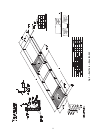
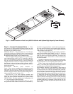
3
1
4
3
2
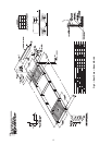
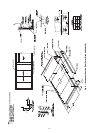
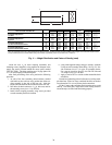
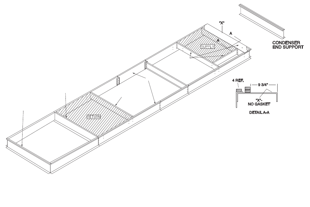
Fig. 8 — Gasket Location on Roof Curb (48P075-100 Units with Optional High-Capacity Power Exhaust)